Understanding the Hourglass Face Proximity Sensor
The hourglass face proximity sensor is a critical component in modern industrial automation and safety systems. It typically utilizes infrared or ultrasonic technology to detect the presence or absence of objects within a specified range, often visualized through an interface display. When this sensor fails to display data, it can halt production lines, compromise safety protocols, and lead to significant operational downtime. The "hourglass face" descriptor usually refers to the icon or graphical representation on the HMI (Human-Machine Interface) that indicates sensor status. A missing display does not always mean the sensor itself is faulty; the issue could stem from electrical connections, software configuration, or environmental interference.
Common Causes of Display Failure
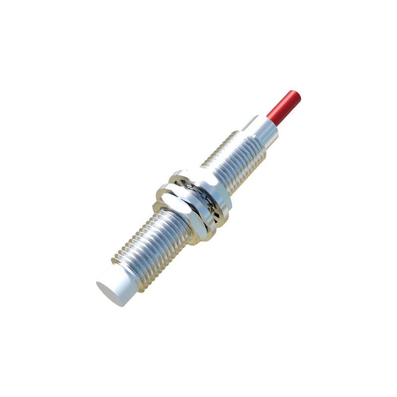
Several factors can cause the proximity sensor's display to not appear. Power supply irregularities, such as voltage drops or surges, are primary suspects. Loose or corroded wiring in the sensor's circuit can interrupt signal transmission to the display unit. Configuration errors in the PLC (Programmable Logic Controller) or HMI software, including incorrect addressing or parameter settings, may prevent data visualization. Environmental conditions like excessive dust, moisture, or electromagnetic interference from nearby machinery can also degrade sensor performance. Additionally, hardware failures in the sensor, display panel, or communication modules (e.g., Profibus, Ethernet/IP) need consideration.
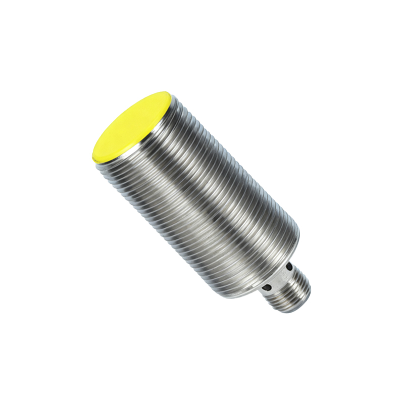
Step-by-Step Diagnostic Procedures
Begin diagnostics by verifying the power supply to both the sensor and display unit. Use a multimeter to check for stable voltage within the manufacturer's specified range. Inspect all physical connections, including cables, terminals, and connectors, for signs of damage, looseness, or corrosion. Next, review the software configuration: confirm the sensor's address in the PLC program matches the HMI tag, and ensure data types and scaling are correctly set. Test the sensor independently by observing its output signal with an oscilloscope or diagnostic tool to see if it triggers appropriately. If the sensor functions but the display doesn't update, focus on the communication link between the PLC and HMI, checking network settings and protocol integrity.
Software and Configuration Checks
Software issues often underlie display problems. Access the HMI configuration software to verify that the sensor's data point is properly linked to a visible element on the screen. Ensure no masking or hiding conditions are active in the program logic. Update or reinstall device drivers and firmware for the sensor and display interface, as outdated versions can cause compatibility glitches. Examine the PLC ladder logic or function blocks for any commands that might inhibit display output, such as reset functions or error-handling routines. Logging into the system's diagnostic menu can provide error codes or alerts that pinpoint software-related failures.
Hardware Inspection and Replacement
If software checks yield no issues, proceed to hardware inspection. Physically examine the proximity sensor for visible damage, contamination, or misalignment. Clean the sensor lens or surface with appropriate materials to remove obstructions. Swap the sensor with a known working unit to isolate the fault—if the display works with the replacement, the original sensor is defective. Similarly, test the display panel by connecting it to a different sensor or system. Check intermediate components like signal conditioners, amplifiers, or communication cards for faults. In cases of persistent failure, consult the sensor's datasheet for specific diagnostic LEDs or output indicators that signal operational status.
Environmental and Interference Mitigation
Industrial environments pose unique challenges. Ensure the sensor is installed away from high-vibration areas, extreme temperatures, or corrosive substances that could affect its electronics. Electromagnetic interference (EMI) from motors, welders, or frequency drives can disrupt sensor signals; use shielded cables, proper grounding, and ferrite cores to mitigate noise. Regularly schedule maintenance to clean and calibrate the sensor, as buildup of dust or debris can attenuate detection capabilities. Consider upgrading to sensors with higher ingress protection (IP) ratings if environmental factors are severe. Document ambient conditions during failures to identify patterns.
Preventive Maintenance Strategies
To avoid future display issues, implement a robust preventive maintenance plan. This includes periodic inspection of all electrical connections, validation of software backups, and calibration of sensors according to manufacturer guidelines. Train personnel on basic troubleshooting steps to enable quick response. Keep spare sensors and communication modules on hand to minimize downtime. Utilize predictive maintenance tools, such as vibration analysis or thermal imaging, to detect potential failures before they impact the display. Regularly update system documentation, including wiring diagrams and configuration files, to streamline diagnostics.
Conclusion and Best Practices
Resolving hourglass face proximity sensor display problems requires a systematic approach, blending electrical, software