Understanding Proximity Sensor Fundamentals
Proximity sensors are non-contact devices designed to detect the presence or absence of an object within a specified sensing range. Unlike mechanical limit switches, they operate without physical contact, offering superior reliability, longevity, and speed. The core principle involves generating an electromagnetic field or beam and detecting changes caused by a target object. These sensors are indispensable in modern industrial automation, robotics, and safety systems, enabling precise control and monitoring. Key performance parameters include sensing distance, repeat accuracy, response frequency, and environmental robustness. A clear grasp of these fundamentals is the first critical step toward effective selection and application in any electrical control system.
Primary Types and Operating Principles

Selecting the right sensor begins with understanding the different technologies available. Inductive proximity sensors detect metallic objects, typically ferrous metals like steel and iron, using an oscillating electromagnetic field. They are highly robust and immune to environmental factors like dust or oil. Capacitive sensors can detect both metallic and non-metallic materials (plastics, wood, liquids) by measuring changes in capacitance. Ultrasonic sensors use sound waves to detect objects and can measure distance, making them suitable for level detection and complex shapes. Photoelectric sensors employ a light beam (visible, infrared, or laser) and are excellent for long-range detection of any material that interrupts or reflects the beam. Each type has distinct advantages, limitations, and ideal application scenarios that must be carefully evaluated.
Key Selection Criteria for Optimal Performance
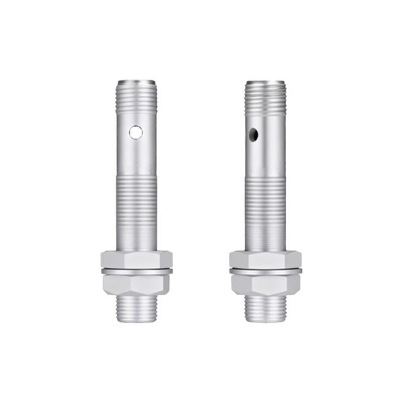
A systematic approach to selection ensures reliable operation. First, define the target material: metal, plastic, liquid, or other. This immediately narrows down the technology choice. Next, determine the required sensing distance, ensuring to account for a safety factor, typically 70-80% of the nominal range listed in datasheets, to accommodate manufacturing tolerances and environmental conditions. The sensor's housing size and form factor (barrel, rectangular, ring) must fit the mechanical installation constraints. Environmental conditions are paramount; consider temperature extremes, presence of chemicals, washdown requirements (IP67/IP69K ratings), and electrical noise. Finally, the electrical output type (NPN/PNP, NO/NC) must be compatible with the controller's input module (PLC, relay). Ignoring any of these criteria can lead to premature failure or erratic system behavior.
Installation and Alignment Best Practices
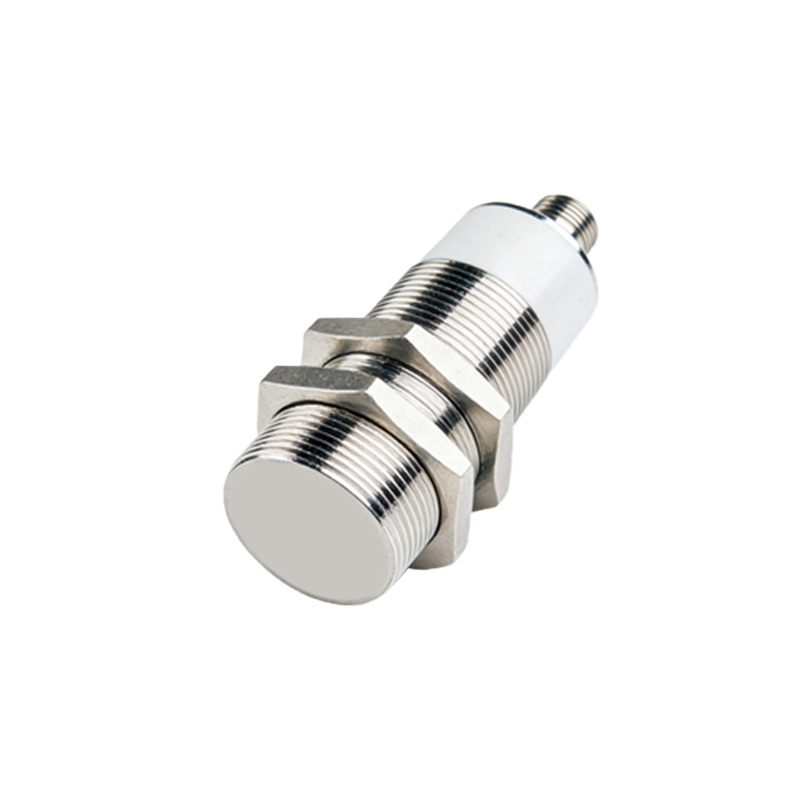
Proper installation is as critical as the selection itself. Always follow the manufacturer's guidelines for mounting distances. For inductive and capacitive sensors, maintain adequate clearance from surrounding metal (the "flush-mountable" feature mitigates this for some inductive types). Ensure the target approaches the sensor's sensing face correctly, as the effective sensing distance can vary with approach direction. For photoelectric and ultrasonic sensors, precise alignment is essential; use alignment tools or indicators provided by the manufacturer. Secure all cabling away from high-noise sources like motor drives and power lines. Implement mechanical protection (brackets, guards) if there is risk of physical damage from the target or other machinery. A well-installed sensor maximizes its rated performance and service life.
Detection Circuitry and Wiring Considerations
The electrical interface is a common source of issues. Two-wire DC sensors connect in series with the load but have a residual leakage current that must be considered for PLC inputs. Three-wire DC sensors (NPN sinking or PNP sourcing) are more common and offer precise switching; ensure the polarity and common wire are connected correctly to the power supply. Always use a stable, regulated power supply within the sensor's voltage range. Incorporate protective devices such as surge suppressors for inductive loads (relays, solenoids) in the circuit to protect the sensor's output transistor. For long cable runs, use shielded cables and ground the shield at the controller end to prevent electromagnetic interference (EMI) from disrupting the signal. Verifying the wiring against the datasheet diagram before power-up prevents costly damage.
Routine Testing and Diagnostic Procedures
Regular testing validates sensor health and system integrity. A simple functional test involves moving a target into and out of the sensing field while monitoring the output state with a multimeter, PLC input indicator, or pilot light. For analog output sensors, measure the output current (4-20mA) or voltage (0-10V) at known distances. Many modern sensors feature built-in diagnostic LEDs that indicate power status and output switching; a constantly lit or unlit LED can indicate wiring faults, power issues, or sensor failure. For photoelectric sensors, lens contamination is a frequent issue; regular cleaning with appropriate solvents is necessary. Keep a log of sensor performance trends to predict failures before they cause unplanned downtime. Advanced networked sensors may offer diagnostic data via IO