Understanding Series Wiring for Proximity Sensors
Wiring proximity sensors in series is a common practice in industrial control systems to create logical AND conditions. This configuration connects the output terminals of two or more sensors sequentially, forming a single current path. When all sensors in the series loop are activated—meaning they detect a target within their sensing range—the circuit closes, allowing current to flow to the load, typically a PLC input module, relay coil, or indicator lamp. This method is fundamentally different from parallel wiring, which creates an OR condition. Series wiring is particularly advantageous in safety circuits and multi-point verification systems where simultaneous activation of all sensing points is mandatory for machine operation or process initiation. It ensures that a process only proceeds when all predefined conditions, monitored by individual sensors, are satisfactorily met.
Key Considerations Before Implementation
Before designing a series circuit, several critical electrical parameters must be verified to ensure reliable operation. First, examine the sensor output type. This configuration is primarily suitable for 3-wire DC sensors with NPN (sinking) or PNP (sourcing) transistor outputs. The sensors in the series must share the same output type; mixing NPN and PNP outputs in one series string will not function. Second, assess the voltage drop. Each conducting sensor output transistor exhibits a small voltage drop (typically 1-2V). When multiple sensors are wired in series, these drops are cumulative. The total voltage at the end of the chain must be sufficient to reliably drive the load. For instance, if using a 24VDC supply and three sensors each with a 1.5V drop, the voltage available for the load reduces to 19.5V, which must still be above the load's minimum operating voltage.
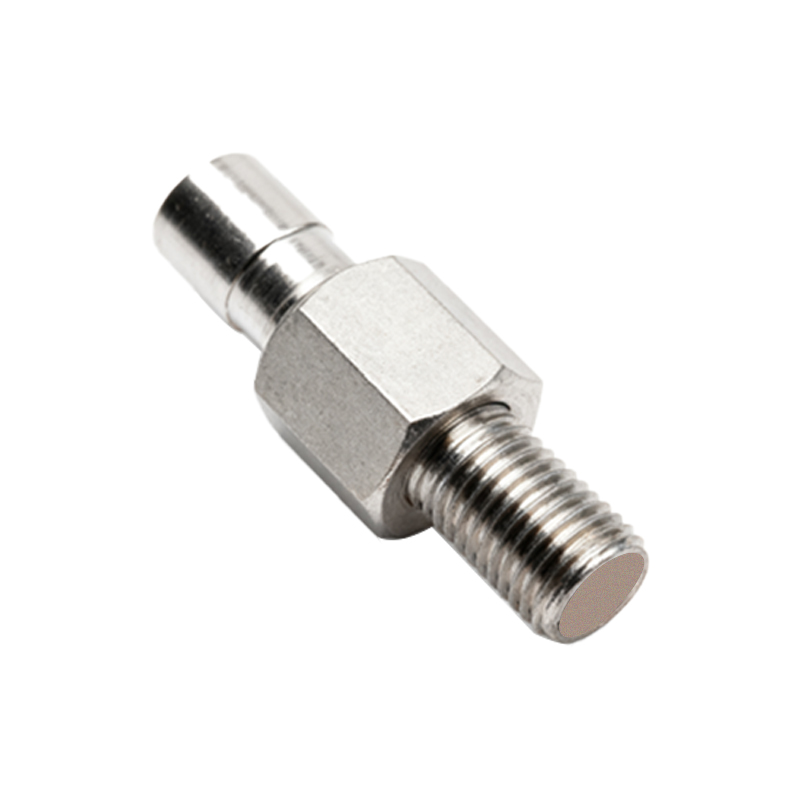
Step-by-Step Wiring Procedure for NPN Sensors
For a series connection of NPN (normally open) proximity sensors, follow this procedure. Connect the brown wire (typically +V) of all sensors to the positive terminal of the DC power supply. Connect the blue wire (typically 0V or common) of all sensors to the negative terminal of the supply. This establishes the power circuit. For the signal circuit, connect the black wire (output) of the first sensor to one terminal of your load (e.g., PLC input). Connect the black wire of the second sensor to the other terminal of the same load. Finally, connect the remaining black wire from the first sensor and the second sensor together. This creates the series path through the output transistors. When both sensors detect a target, their internal transistors conduct, completing the circuit from the load, through both sensors, to the power supply negative, thus activating the load.
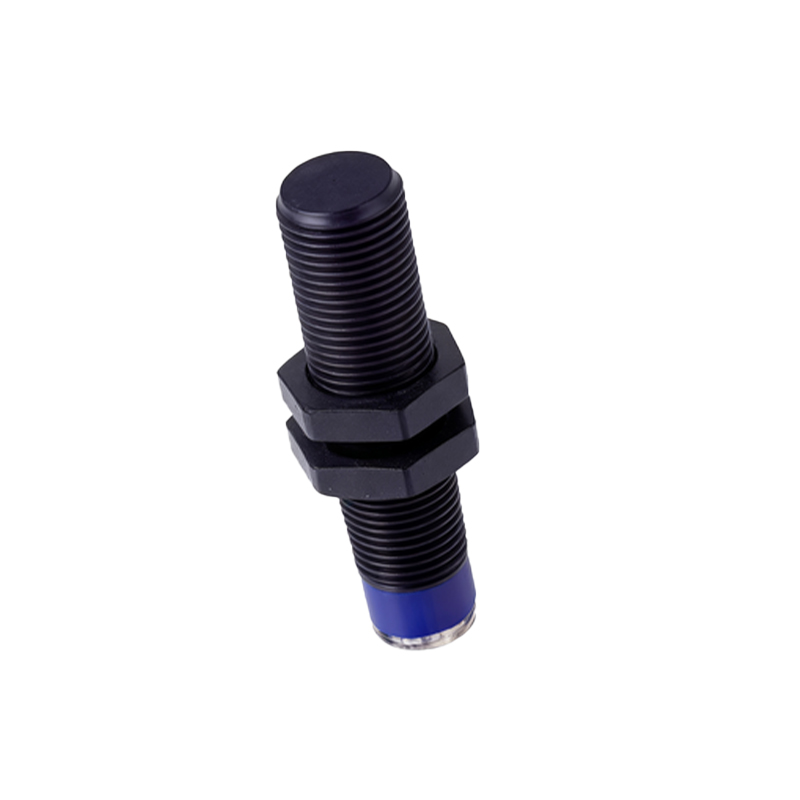
Step-by-Step Wiring Procedure for PNP Sensors
The series wiring logic for PNP (normally open) sensors is similar but with a reversed current path. Connect the brown wire (+V) and blue wire (0V) of all sensors to the power supply as before. For the signal circuit, connect the black wire (output) of the first sensor to the positive side of the power supply. Then, connect the black wire of the second sensor to one terminal of the load. Finally, connect the remaining black wire from the first sensor and the second sensor together. In this configuration, when both PNP sensors are activated, current flows from the supply positive, through the first sensor's output transistor, through the connection to the second sensor's output transistor, through the load, and finally to the supply negative. The load is powered only when both output transistors are conducting.
Calculating Load Compatibility and Current Limits
A crucial step is verifying that the total load current does not exceed the maximum switching current (Ic) of any sensor in the chain, especially the first sensor which carries the full load current. Check the datasheet for the sensor's maximum continuous output current rating. If the load draws 100mA and each sensor is rated for 200mA, the setup is acceptable. However, if the load current is 150mA and a sensor is rated for 100mA, the first sensor will be overloaded. Furthermore, consider the inrush current of inductive loads like relay coils. Always include a safety margin. It is often prudent to use an interposing relay with a low coil current as the primary load, which then controls higher-power circuits, thereby protecting the sensor outputs from excessive current.
Advantages and Practical Applications
The primary advantage of series wiring is enhanced safety and process control through conditional logic. A classic application is in machine guarding: two safety curtains or multiple safety mats can be wired in series so that the machine stops only if all guarding zones are breached simultaneously, or conversely, a machine