Introduction to Proximity Sensing in Motorcycles
Modern motorcycles are sophisticated machines where electronic control systems play a pivotal role in performance, safety, and rider experience. At the heart of many of these systems are proximity switch sensors. These non-contact sensors detect the presence or absence of a metallic target without physical touch, providing critical input to the Engine Control Unit (ECU), anti-lock braking system (ABS), traction control, and other vital subsystems. Their reliability, durability, and precision make them indispensable in the harsh operating environment of a motorcycle, which is subject to extreme vibrations, temperature fluctuations, moisture, and contaminants.
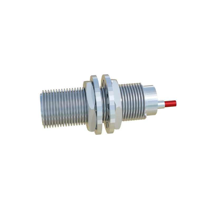
Operating Principles and Core Technologies
The predominant technology used in motorcycle applications is the inductive proximity sensor. This sensor generates an oscillating electromagnetic field from a coil wound around a ferrite core. When a ferrous metal target, such as a gear tooth or a reluctor ring, enters this field, eddy currents are induced in the target. This causes a change in the oscillation amplitude within the sensor, which is detected by an internal circuit. The circuit then switches the output state, typically from a high to a low voltage signal, providing a clean, digital pulse to the monitoring system. Hall-effect sensors are also employed, particularly for camshaft and crankshaft position sensing, where they detect changes in magnetic field strength caused by a rotating target.
Key Applications and System Integration
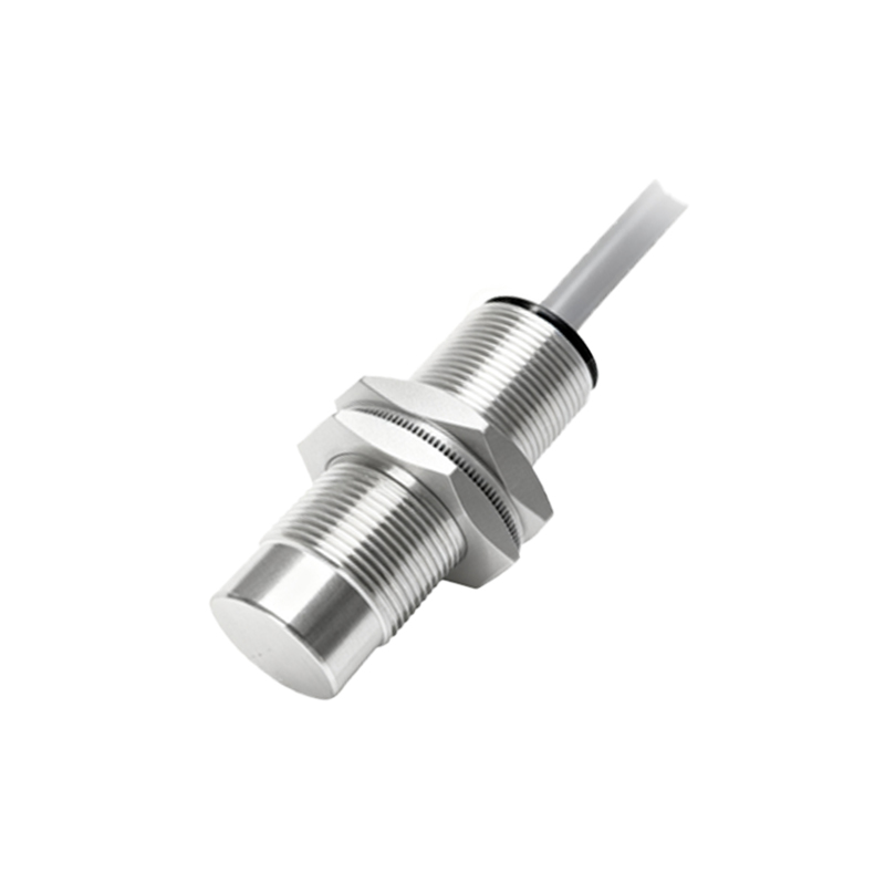
The integration of proximity sensors is widespread. A primary application is engine speed and position sensing. Sensors mounted near the crankshaft or camshaft detect passing teeth on a reluctor wheel, providing the ECU with precise timing data for fuel injection and ignition spark. In the chassis, these sensors are fundamental to ABS and traction control systems. They monitor wheel speed by detecting targets on the wheel hub or brake disc carrier. This real-time speed data allows the system to compare wheel speeds and prevent lock-up or loss of traction. Other uses include gear position indication, side stand detection for safety interlocks, and clutch lever position sensing for features like quick-shifters.
Design Considerations for Harsh Environments
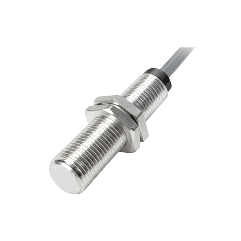
Engineering a proximity sensor for motorcycle use demands rigorous design criteria. The housing must be robust, typically constructed from stainless steel or high-grade engineering plastics, with an ingress protection (IP) rating of at least IP67 to withstand high-pressure water jets and dust. Internal components are potted with epoxy resin to resist shock and vibration, which can exceed 10g in certain conditions. Operating temperature range is critical, with specifications often spanning from -40°C to +150°C to account for engine bay heat and winter riding. Electrical characteristics, such as supply voltage range (commonly 5V or 12V), output type (PNP/NPN, digital, or analog), and switching frequency, must be meticulously matched to the vehicle's electrical architecture.
Installation, Alignment, and Air Gap
Proper installation is paramount for sensor performance and longevity. The most critical parameter is the air gap—the distance between the sensor's active face and the target. Each sensor has a specified nominal sensing distance (Sn), and the operational air gap is typically set to 50-80% of Sn to account for mechanical tolerances, thermal expansion, and bearing play. Precise alignment is necessary to ensure consistent signal strength. Mounting must be secure to prevent loosening from vibration, often using locking nuts or thread-locking compounds. The target geometry, material, and size must conform to the sensor's specifications to guarantee reliable switching.
Diagnostics and Failure Mode Analysis
Proximity sensor failures, while uncommon, can lead to drivability issues or system shutdowns. Common failure modes include physical damage from impact, internal circuit failure due to voltage spikes or thermal stress, and signal degradation from contamination (e.g., metallic shavings adhering to the sensor face). Diagnostic procedures involve checking supply voltage, measuring output signal with an oscilloscope to inspect waveform integrity (amplitude and shape), and verifying the air gap. An erratic or missing signal often points to a faulty sensor, incorrect gap, or a damaged target wheel. Implementing proper shielding for the signal cable is also essential to prevent electromagnetic interference (EMI) from ignition systems.
Future Trends and Smart Sensor Integration
The evolution of motorcycle electronics is driving advancements in sensor technology. The trend is towards "smarter" sensors with integrated diagnostics that can communicate fault codes directly to the ECU. Miniaturization allows for packaging in tighter spaces without sacrificing performance. Furthermore, the rise of electric motorcycles and advanced rider assistance systems (ARAS) will create new applications. For instance, proximity sensors may be used in battery management systems for contactor