Understanding Proximity Sensors with Alarm Functionality
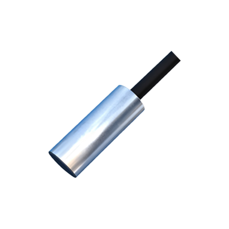
Proximity sensors with integrated alarm functions represent a sophisticated evolution in industrial sensing technology. These devices combine the standard non-contact detection capabilities of inductive, capacitive, or photoelectric sensors with an onboard alert system. The primary purpose is not only to detect the presence or absence of a target object but also to provide an immediate, local indication of a specific condition or fault. This condition is typically a change in the sensor's operational status that deviates from its normal parameters. The alarm is often a built-in audible buzzer or a visual LED indicator that activates under predefined circumstances, such as a wiring error, a short circuit, an overload condition, or when the sensor operates outside its specified sensing range. This integrated diagnostic feature significantly enhances maintenance efficiency and system reliability by providing instant, on-site feedback without requiring connection to a central controller for status reading.
Common Reasons for Alarm Activation
Several specific operational issues can trigger the alarm on a proximity sensor. One of the most frequent causes is incorrect wiring or power supply problems. If the sensor is connected with reverse polarity or if the supplied voltage falls outside the rated operating range (e.g., under-voltage or over-voltage), the internal protection circuit will often activate the alarm. Another common trigger is an output overload or short circuit. When the sensor's output transistor is subjected to a current exceeding its maximum rating—due to a short in the load wiring or an overly high inrush current from the connected device—the sensor protects itself by shutting down the output and sounding the alarm. Furthermore, excessive temperature beyond the sensor's specified environmental limits can cause an alarm. This might occur if the sensor is installed too close to a heat source or in an enclosure without proper ventilation. Finally, some advanced models feature "teach-in" functionality and may alarm if the background or target material has changed significantly, indicating a need for recalibration.
Diagnosing and Troubleshooting Alarm States

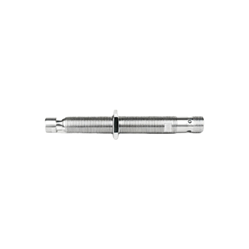
A systematic approach is essential for diagnosing an active alarm on a proximity sensor. First, consult the specific sensor's datasheet or manual. The meaning of the alarm (e.g., a specific LED flash pattern or buzzer sequence) is manufacturer and model-dependent. The initial step is always to verify the power supply. Use a multimeter to confirm that the voltage at the sensor's terminals matches the required specifications and that the polarity is correct. Next, inspect the load circuit. Disconnect the load from the sensor's output and reset the power. If the alarm ceases, the fault lies in the load wiring or the device itself—check for short circuits, excessive current draw, or incompatible load types (e.g., using an NPN sensor to drive a PNP logic input). If the alarm persists with no load, the issue may be internal to the sensor. Also, examine the sensing environment for contaminants like metal chips, dust, or oil buildup on the sensing face, which can cause erratic behavior and trigger diagnostic alarms. Ensure the target object is within the specified sensing distance and is made of the correct material (ferrous metal for inductive sensors).
Configuration and Setup to Prevent False Alarms
Proper installation and configuration are critical to preventing nuisance alarms. Ensure the sensor is mounted securely, with the correct orientation and adequate clearance from other metal objects as specified by the manufacturer to avoid mutual interference. For adjustable sensors, set the sensing distance and hysteresis correctly using the prescribed method (e.g., a teach-button or potentiometer). Pay close attention to the output configuration (NPN sinking vs. PNP sourcing) and ensure it matches the input module of your PLC or controller. When wiring, use shielded cables in electrically noisy environments and ground the shield properly at one end to prevent electromagnetic interference (EMI) from causing false triggers or alarm states. For sensors in harsh environments, select a model with an appropriate IP (Ingress Protection) rating and correct housing material (e.g., stainless steel for washdown areas). Implementing these best practices during the initial setup minimizes the risk of operational faults that lead to alarms.
Advanced Features and Integration
Modern proximity sensors with alarm capabilities often include advanced communication protocols like IO-Link. IO-Link transforms a standard binary sensor into an intelligent device capable of transmitting detailed diagnostic data, parameter settings, and process values to the control system. Through IO-Link, the specific reason for an alarm—such as "overcurrent," "undervoltage," or "temperature warning"—can be transmitted directly to the PLC and visualized on an HMI, enabling predictive maintenance. Furthermore, parameters like switching distance, output delay, and alarm thresholds can be configured remotely via software, reducing downtime for adjustments. Some sensors also feature programmable multi-color LEDs that indicate different states (power, signal