Fundamental Operating Principle
Capacitive proximity sensors operate on the principle of capacitance change. At their core, they consist of an oscillator circuit, a sensing surface (electrode), and a signal evaluation unit. The sensor's active face and the target object form the two plates of a capacitor, with the intervening space acting as the dielectric. When no target is present, the oscillator is inactive. As a target object approaches the sensing face, it alters the dielectric constant of the surrounding space, increasing the capacitance of the system. Once this capacitance reaches a specific threshold, it triggers the oscillator to start. The subsequent signal is processed by the evaluation circuitry, which then switches the sensor's output state. This non-contact detection method is effective for a wide range of materials, including metals, plastics, glass, wood, and liquids, as all substances have a dielectric constant different from air.
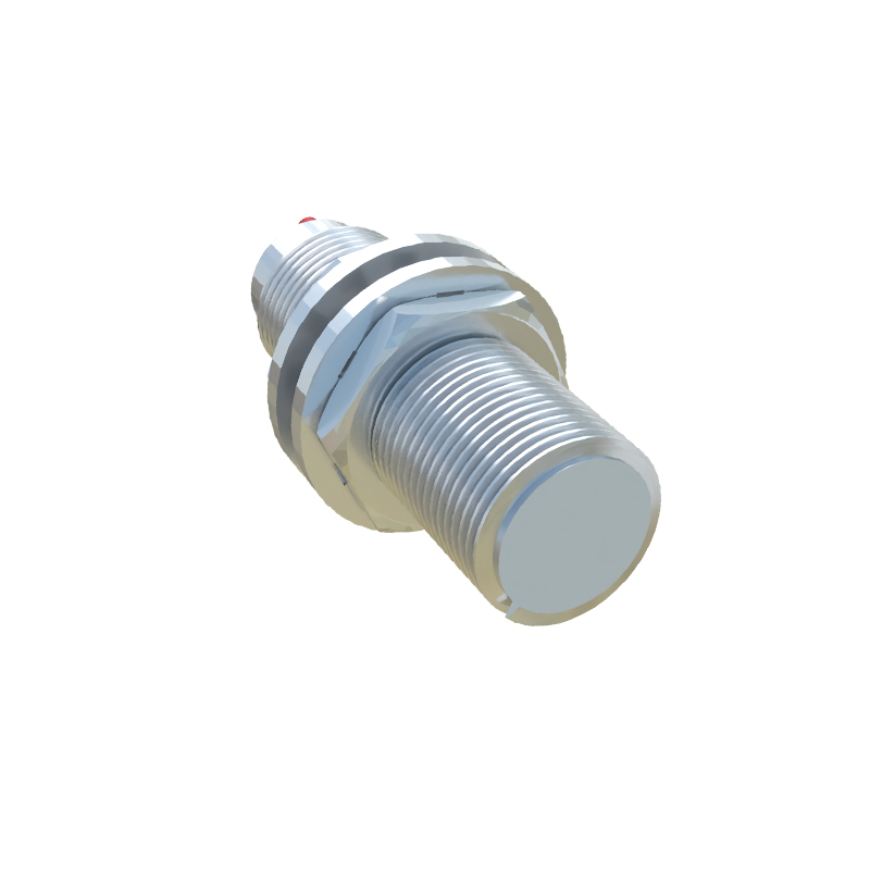
Key Design Components and Characteristics
The performance of a capacitive sensor is defined by several critical components. The sensing electrode's size and shape directly influence the sensing range and field shape. A shielding electrode, often surrounding the active face, is crucial for creating a focused electrostatic field, preventing the sensor from being influenced by surrounding conductive materials and ensuring stable, repeatable operation. The oscillator frequency and the sophistication of the signal processing unit determine sensitivity and response time. Key specifications include the nominal sensing range (Sn), typically from a few millimeters to about 40mm for standard models, and the repeatability, which is exceptionally high. These sensors often feature a potentiometer for sensitivity adjustment, allowing the user to fine-tune the detection threshold to ignore background interference or detect materials with low dielectric constants.
Comparison with Inductive Proximity Sensors
A common point of analysis is the distinction between capacitive and inductive proximity sensors. Inductive sensors detect only metallic objects by generating an electromagnetic field. They are generally immune to non-metallic contaminants like dust or water films. Capacitive sensors, in contrast, respond to any material that disrupts their electrostatic field. This makes them versatile but also more susceptible to false triggers from environmental changes such as humidity, condensation, or buildup of material on the sensor face. For pure metal detection in industrial environments, inductive sensors are often preferred for their robustness. Capacitive sensors are the clear choice for non-metallic target detection, level sensing of liquids or granules, or applications requiring detection through a non-metallic container wall.
Primary Industrial Applications
The unique capability of capacitive sensors leads to their deployment in diverse applications. A major use case is level detection and control. They are ideal for monitoring the fill level of liquids, powders, pellets, or granules inside tanks, hoppers, or silos, often through a plastic or glass wall. In packaging, they detect the presence of plastic bottles, glass vials, or cardboard boxes on a conveyor. They are used in woodworking to sense wood panels and in the food industry to detect the presence of products regardless of packaging material. Furthermore, they serve in touch-sensitive interfaces and as non-contact switches. Their ability to ignore metallic backgrounds when properly adjusted makes them suitable for complex assembly verification tasks.
Critical Selection and Installation Guidelines
Selecting the correct capacitive sensor requires careful consideration of several factors. First, identify the target material and its dielectric constant; lower constants require a more sensitive sensor. The required sensing distance must be derated from the catalog specification, typically using a factor of 0.7 to 0.8 for reliable operation under real-world conditions. The housing material (typically PTFE, PP, or stainless steel) must be compatible with the environment, considering factors like chemical exposure, temperature extremes, and pressure washdowns. During installation, it is vital to ensure the sensor has sufficient clearance from any surrounding metal (as specified by the manufacturer) to prevent shielding effects. The sensitivity potentiometer should be adjusted with the target at the desired switching point, not when it is extremely close. For liquid level sensing, mounting the sensor horizontally on the side of a tank often provides more reliable detection than vertical top-down mounting.
Troubleshooting Common Operational Issues
Even well-selected sensors can encounter problems. Unstable switching or false outputs are frequently caused by environmental factors. Condensation, dust, or material adhering to the sensing face changes the local dielectric constant. Cleaning the face and, if possible, using a sensor with a smooth face to prevent buildup is recommended. Electrical interference from variable frequency drives or large motors can be mitigated by using shielded cables, proper grounding, and ensuring power supply stability. If the sensor fails to detect a target, verify the actual dielectric constant, ensure the target is within the adjusted sensing range, and check that the sensitivity is not set too low.