Fundamentals of Proximity Speed Sensing
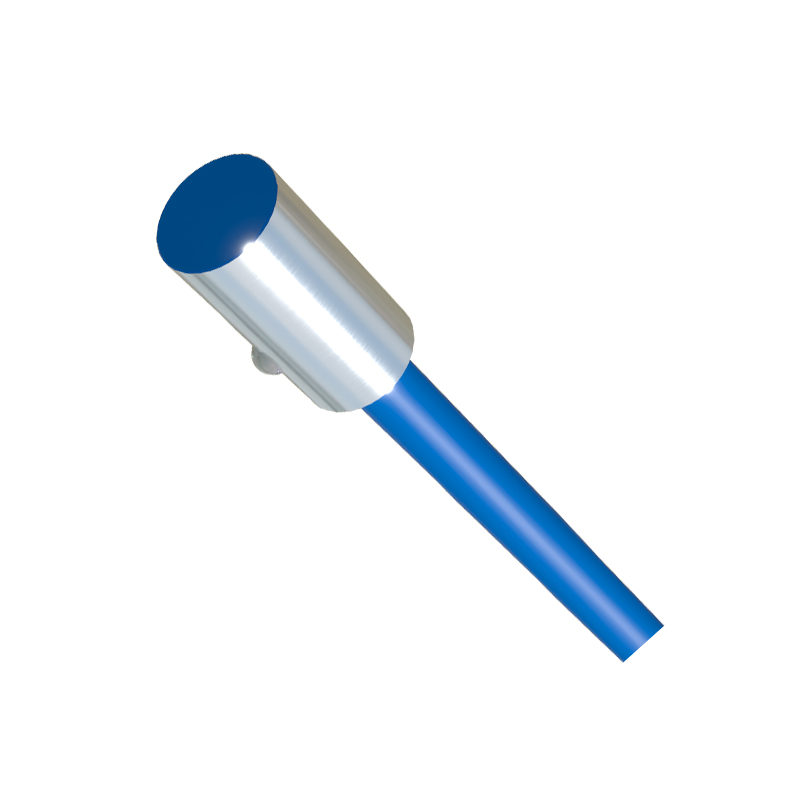
Proximity three-wire speed sensors are pivotal components in modern industrial automation and machinery monitoring. These devices operate on the principle of detecting the presence or absence of a metallic target, typically a gear tooth, keyway, or specially mounted tab, without making physical contact. The core sensing technology is often based on the eddy current principle. An oscillator circuit within the sensor generates a high-frequency electromagnetic field at its active face. When a ferrous or non-ferrous conductive target enters this field, eddy currents are induced on the target's surface. These currents absorb energy from the oscillator, causing a change in its amplitude. This change is detected and converted into a clean, digital output signal. The "three-wire" designation refers to the standard wiring configuration: one wire for DC supply voltage (typically 10-30 VDC), one wire for the output signal, and one wire for the common ground or 0V reference. This setup allows for a robust switching signal, commonly an NPN (sinking) or PNP (sourcing) transistor output, which is ideal for interfacing directly with programmable logic controllers (PLCs), frequency counters, or tachometers.
Key Advantages in Industrial Environments
The adoption of three-wire proximity sensors for speed measurement offers several compelling advantages over mechanical or optical alternatives. Their non-contact nature eliminates wear and tear, ensuring exceptionally long service life and reducing maintenance downtime. They are inherently robust, capable of operating in harsh conditions filled with oil, coolant, dust, and vibration—commonplace in manufacturing plants, pulp and paper mills, and mining operations. Unlike optical encoders, they are unaffected by ambient light or opaque contaminants. The solid-state electronic output provides a fast response time and high switching frequency, enabling accurate detection of very high rotational speeds. Furthermore, their simple installation—requiring only a bracket mount opposite a rotating target—makes them a cost-effective and reliable solution for a vast array of speed-sensing and overspeed/underspeed protection applications on conveyors, turbines, motors, and gearboxes.
Critical Selection Parameters for Engineers
Selecting the correct three-wire speed sensor requires careful consideration of several technical parameters to ensure reliable system integration. First, the sensing distance or range must be specified, ensuring the target passes within this range during operation. Engineers must also consider the target material, size, and geometry, as these affect the sensor's effective switching point. The output type (NPN vs. PNP) must match the input card of the controlling device (e.g., PLC). Key electrical specifications include the operating voltage range, current consumption, and output current capacity. The housing material is critical for chemical resistance; stainless steel is a common choice. For speed measurement, the sensor's maximum switching frequency (in Hz) must exceed the maximum anticipated pulse frequency generated by the target. This frequency is calculated based on the maximum rotational speed (RPM) and the number of targets per revolution. Environmental ratings, such as IP (Ingress Protection) and temperature range, are non-negotiable for ensuring performance in the intended operating climate.
Installation and Configuration Best Practices
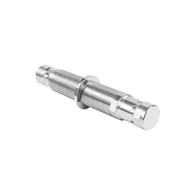
Proper installation is paramount for optimal performance and accuracy. The sensor should be mounted securely to minimize vibration, which can cause signal instability. The alignment between the sensor's active face and the target is crucial; misalignment can reduce the effective sensing distance and cause inconsistent pulses. A standard practice is to install the sensor with an air gap slightly less than the nominal sensing range to account for potential axial play in the rotating shaft. Electrical wiring must follow manufacturer guidelines, with attention to proper shielding if cable runs are long or in electrically noisy environments. The brown wire (typically +V), blue wire (0V), and black wire (output) must be connected correctly to prevent damage. For speed monitoring, the output signal is fed into a frequency measuring device. It is often necessary to configure a debounce filter or a minimum pulse width setting in the monitoring equipment to eliminate electrical noise or mechanical chatter from causing false counts, ensuring a clean and accurate speed reading.
Common Applications Across Industries
The versatility of three-wire proximity speed sensors makes them ubiquitous. In automotive manufacturing, they monitor the speed of robotic arms, conveyor chains, and spindle drives. Within the power generation sector, they are used for turbine overspeed protection and pump shaft monitoring. On wind turbines, they provide vital rotor speed data for pitch control systems. In material handling, they monitor belt conveyor speeds for synchronization and slip detection. They are integral to paper machines for monitoring roll speeds and in printing presses for ensuring registration accuracy. Furthermore, they serve as simple yet effective zero-speed switches;