Understanding Hall Effect Proximity Sensors
Hall Effect proximity sensors are solid-state devices that detect the presence of a magnetic field. Unlike inductive sensors, they require a magnetic target, typically a permanent magnet. The core principle is the Hall Effect: when a current-carrying conductor is placed in a magnetic field, a voltage (the Hall voltage) is generated perpendicular to both the current and the field. The sensor's integrated circuit processes this signal to provide a clean, digital or analog output. This technology offers key advantages, including the ability to detect static magnetic fields, high switching frequencies, and excellent resistance to environmental factors like dust, oil, and non-ferrous contaminants. Understanding this operational basis is crucial for correct application and installation.
Pre-Installation Planning and Considerations
Thorough planning prevents operational failures. First, confirm the sensor type (e.g., 3-wire DC PNP/NPN, analog output) matches your control system's input requirements. Verify the voltage supply range (commonly 10-30V DC). Next, select an appropriate target. The sensor's datasheet specifies the nominal sensing distance (Sn). For reliable operation, the effective sensing distance should be 70-80% of Sn to account for temperature drift and manufacturing tolerances. The target must be a suitable magnet (e.g., neodymium) with the correct pole orientation facing the sensor's active surface. Consider the operating environment: ensure the sensor's housing rating (IP67, IP69K, etc.) is suitable for the presence of moisture, chemicals, or washdowns. Finally, plan the mounting location to avoid interference from stray magnetic fields from motors, transformers, or power cables.
Mechanical Mounting Procedures
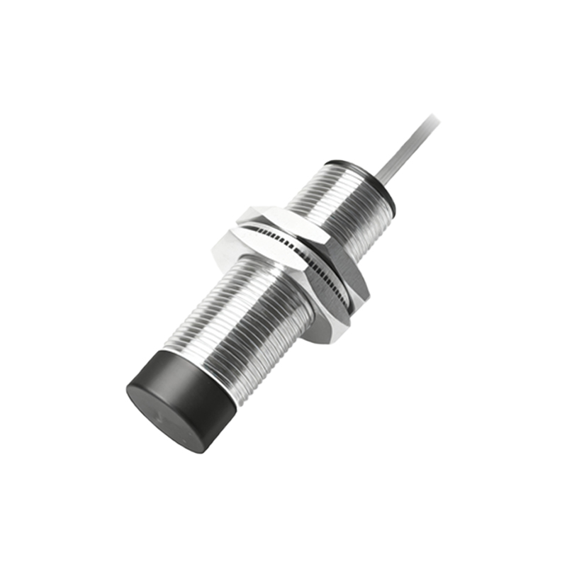
Secure and stable mounting is paramount. Use the recommended mounting hardware, typically provided with the sensor. For cylindrical sensors, use the correct locknut and a calibrated torque wrench to avoid damaging the housing. Flush-mountable sensors can be installed in metal, but non-flush models require a non-ferrous collar to prevent shielding effects. Ensure the sensor is rigidly fixed to minimize vibration, which can cause false triggering or physical damage. The sensing face must be aligned parallel to the target's approach path. Maintain the recommended gap between the sensor body and the target's travel path to prevent physical collision. For applications with lateral target movement, refer to the datasheet for lateral offset tolerances. Always leave sufficient space for wiring connections and future maintenance access.
Electrical Wiring and Connection
Incorrect wiring is a leading cause of sensor failure. Always disconnect power before making connections. For a standard 3-wire DC sensor: connect the brown wire (+V), blue wire (0V/GND), and the black wire (output signal) to the corresponding PLC input or relay. Double-check PNP (sourcing) vs. NPN (sinking) configuration. Use shielded cable in electrically noisy environments, connecting the shield to ground at the controller end only to avoid ground loops. Keep sensor cables separate from high-voltage AC power lines. If using cable extensions, ensure they are of equivalent quality and rating. For current-sinking outputs, remember to connect the load between the output and positive supply. After wiring, visually inspect for loose strands, correct ferrule crimps, and secure cable gland seals to maintain the IP rating.
Alignment and Air Gap Adjustment
Precise alignment ensures consistent switching. After mounting, manually cycle the target through its full range of motion. Use a non-ferrous feeler gauge or shim to set the initial air gap slightly less than the rated operating distance. Monitor the output with a multimeter or PLC indicator. The sensor must switch reliably at the desired point without chattering. For axial approaches, ensure the target magnet's center passes over the center of the sensing face. For lateral sensing, verify the switch-on point remains stable across the entire travel. If adjustment is needed, slightly loosen the mounting, reposition, and re-tighten. In critical applications, use an oscilloscope to check the output signal's rise time and cleanliness. Document the final gap setting for future reference.
Functional Testing and Troubleshooting
Comprehensive testing validates the installation. Perform a power-on test with the target absent, confirming the output state is OFF (or at the specified null level for analog sensors). Introduce the target to the sensing point and verify a crisp output state change. Repeat this cycle numerous times at the operational speed to check for missed detections. Common issues include no output (check power, wiring, and target strength/magnetism), inconsistent switching (check alignment, voltage supply stability, or EMI), and premature failure (verify environmental ratings and load compatibility). If the sensor