Understanding Inductive Proximity Sensor Fundamentals
Inductive proximity sensors are non-contact devices used to detect the presence of metallic objects. They operate on the principle of electromagnetic induction, where an oscillator generates a high-frequency electromagnetic field from a coil at the active face. When a ferrous or non-ferrous metal target enters this field, eddy currents are induced in the target, causing a change in the oscillation amplitude. This change is detected by the sensor's circuitry, which then switches the output state. The core components include the oscillator, detection circuit, and output switching element. These sensors are valued for their robustness, long service life, and ability to function in harsh industrial environments without physical contact, making them ideal for applications like position sensing, counting, and machine automation.
Key Electrical Standards and Directives
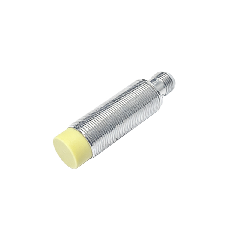
Compliance with international electrical standards is paramount for safety and market access. Key standards include IEC 60947-5-2, which specifies requirements for proximity sensors, covering aspects like dielectric properties, constructional requirements, and performance under various environmental conditions. For the European market, the Low Voltage Directive (LVD) 2014/35/EU and the Electromagnetic Compatibility (EMC) Directive 2014/30/EU are mandatory. The LVD ensures electrical equipment operates safely within specified voltage limits, while the EMC Directive ensures the sensor does not emit excessive electromagnetic interference and is immune to interference from other equipment. Adherence to these standards mitigates risks of electric shock, fire, and operational failure.
Wiring and Connection Requirements
Proper wiring is critical for electrical safety and sensor functionality. Most inductive proximity sensors are available in 2-wire, 3-wire, or 4-wire configurations, with DC or AC supply options. For 3-wire DC sensors, which are common, correct polarity must be observed: brown wire to positive (+), blue wire to negative (-), and black wire as the switched output. The power supply voltage must match the sensor's rated voltage (e.g., 10-30 VDC) to prevent damage. Cables should be shielded to reduce electromagnetic interference, and connections must be secure using appropriate terminals to avoid loose contacts that could cause arcing or overheating. Conduit entries should be properly sealed if used in wet or dusty environments to maintain insulation integrity.
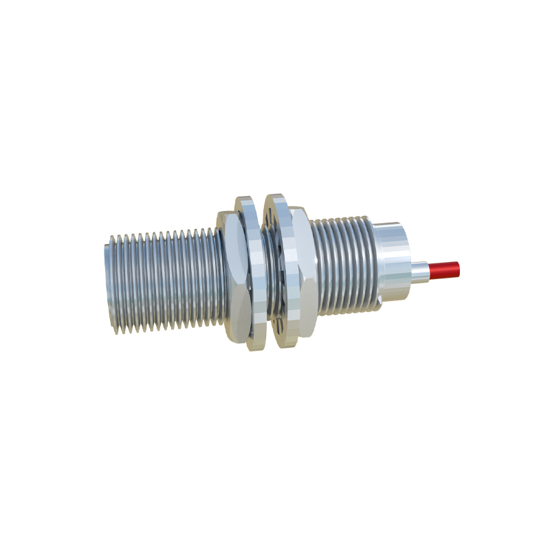
Protection Against Overcurrent and Short Circuits
Sensors must be protected from electrical faults. Incorporating fuses or circuit breakers in the supply line is essential. The protection device should be rated slightly above the sensor's maximum operating current but below the cable's current-carrying capacity. Many sensors feature built-in short-circuit protection, which safeguards the output transistor from damage if the output is accidentally shorted to ground or supply. Additionally, reverse polarity protection is often included in DC sensors to prevent damage if wires are connected incorrectly. These protective measures ensure the sensor remains operational and safe even under fault conditions, enhancing system reliability.
Ensuring Proper Grounding and Shielding
Effective grounding and shielding are vital for noise immunity and EMC compliance. The sensor's metal housing, if present, should be connected to earth ground via a low-impedance path to dissipate any stray currents and reduce electromagnetic emissions. For shielded cables, the shield should be grounded at one end only, typically at the controller or power supply side, to prevent ground loops. In environments with high electromagnetic noise, such as near variable frequency drives or welding equipment, using sensors with higher immunity ratings and ensuring proper separation from noise sources are necessary. This practice minimizes false triggering and ensures stable operation.
Environmental Considerations and Insulation
Electrical compliance extends to environmental resilience. Sensors should have adequate Ingress Protection (IP) ratings (e.g., IP67) to withstand dust and temporary immersion, which helps maintain insulation resistance. The insulation materials used in the sensor must resist degradation from moisture, oils, and chemicals commonly found in industrial settings. Dielectric strength, tested according to standards, ensures the insulation can withstand high voltages without breakdown. Operating temperature ranges must be observed, as extreme heat can weaken insulation, while cold can make materials brittle, potentially leading to electrical faults.
Testing and Certification Procedures
To verify compliance, rigorous testing is conducted. This includes dielectric strength tests, where high voltage is applied between live parts and the enclosure to check for insulation breakdown. Insulation resistance tests measure the resistance between conductive parts. EMC testing involves emissions tests (e.g., radiated and conducted emissions) and immunity tests (e.g., electrostatic discharge, surge immunity). Manufacturers often obtain third-party certifications from bodies like UL, CE, or TÜV