Introduction to Metal Proximity Switch Sensors
Metal proximity switch sensors are fundamental components in modern industrial automation, providing non-contact detection of metallic objects. These devices operate on the principle of electromagnetic induction or capacitive sensing, generating an output signal when a metal target enters their sensing field. Their robustness, reliability, and ability to function in harsh environments—filled with dust, oil, or moisture—make them indispensable in manufacturing, packaging, material handling, and automotive assembly lines. Unlike mechanical limit switches, they have no moving parts to wear out, ensuring long service life and minimal maintenance. The core of their functionality lies in the sophisticated electronic circuit that drives the sensing oscillator, processes the signal, and delivers a clean, switch-like output to control systems like PLCs (Programmable Logic Controllers).
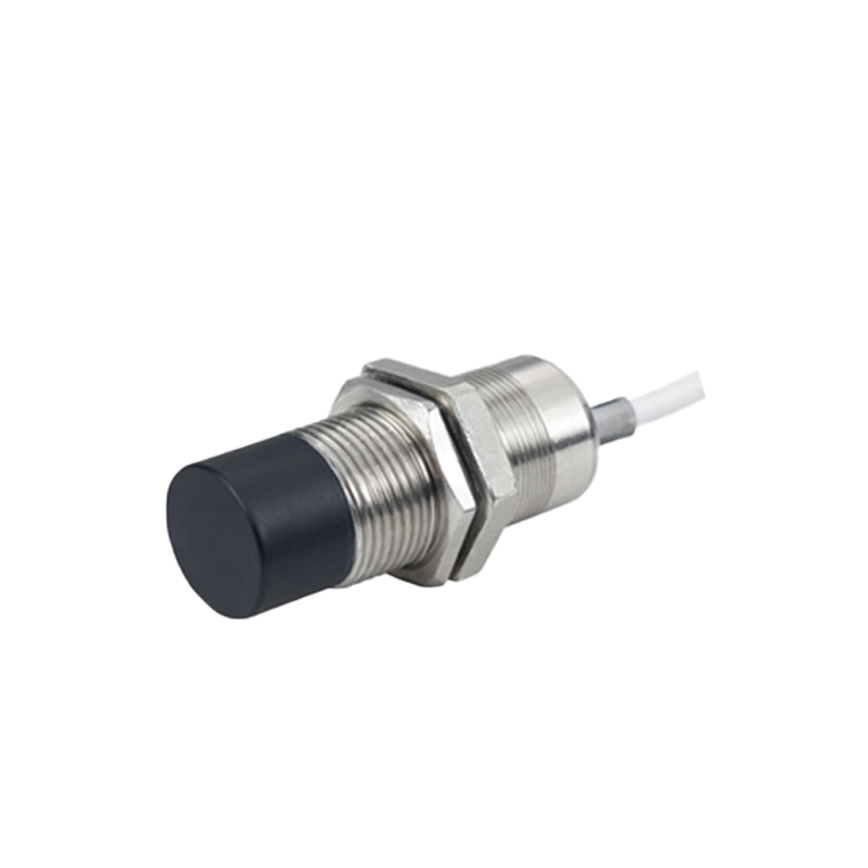
Core Circuit Components and Operating Principle
The typical circuit of an inductive metal proximity sensor comprises several key stages. The heart is an LC oscillator circuit, where 'L' represents the sensing coil (often housed in the sensor's face) and 'C' is a capacitor. This oscillator generates a high-frequency electromagnetic field. When a metallic object enters this field, eddy currents are induced on the surface of the metal. These currents draw energy from the oscillator, causing a drop in the oscillation amplitude. A subsequent demodulation circuit converts this amplitude change into a DC voltage signal. This signal is then fed into a threshold comparator or Schmitt trigger circuit. Once the signal surpasses a predefined threshold, the comparator switches the state of the output driver circuit.
Output Configuration and Interface Circuits
The output stage is critical for interfacing with control systems. Common configurations include NPN (sinking) and PNP (sourcing) transistor outputs for DC sensors, and solid-state or relay outputs for AC models. In a typical NPN circuit, the output transistor connects the load between the supply voltage and the output terminal, sinking current to ground when active. The circuit includes protection elements like flyback diodes for inductive loads (e.g., relays, solenoids) to suppress voltage spikes, and current-limiting resistors. For analog or IO-Link capable sensors, the circuit includes additional digital-to-analog converters and communication protocol chips to provide continuous distance measurement or parameter configuration, moving beyond simple binary detection.
Shielding, Sensitivity, and Circuit Design Considerations
A major design challenge is preventing unwanted detection of surrounding metal, like the sensor's mounting bracket. This is addressed through shielding. A shielded (flush-mountable) sensor incorporates a metal ring around the sensing coil, concentrating the electromagnetic field axially forward. This allows it to be embedded in metal without triggering. Circuit design must also account for sensitivity adjustment, often via a potentiometer or teach-in function, to set the optimal detection range for different metals (steel, aluminum, copper). Aluminum and copper, being non-ferrous, have different effects on the oscillator (affecting both amplitude and frequency) compared to ferrous steel, which some advanced circuits can differentiate.
Power Supply and Protection Circuitry
Reliable operation demands a stable power supply and robust protection. The internal circuit includes a voltage regulator to maintain consistent operation despite supply fluctuations. Essential protection features integrated into the circuit include reverse polarity protection, often using a series diode or a MOSFET-based circuit, to prevent damage if wires are connected incorrectly. Short-circuit protection is implemented in the output stage, automatically limiting current if the output is accidentally shorted to ground or supply. Additionally, surge protection devices like varistors or TVS diodes are used to guard against voltage transients on both power and output lines, ensuring electromagnetic compatibility (EMC) and longevity in electrically noisy industrial settings.
Application-Specific Circuit Variations
Circuit designs vary based on application specifics. High-speed counting applications require sensors with extremely fast response times, achieved through optimized oscillator and comparator circuits with minimal hysteresis. For weld-field immunity, sensors designed for use near resistance welding machines incorporate special filtering circuits that ignore the high-frequency electrical noise generated during welding. Intrinsically safe versions, used in hazardous areas, include energy-limiting barrier circuits that prevent any spark capable of igniting flammable atmospheres. These specialized circuits ensure the sensor performs reliably under unique and demanding operational conditions.
Troubleshooting Common Circuit-Related Issues
Understanding the internal circuit aids in troubleshooting. Failure to detect any metal may indicate a broken oscillator coil or a failed component in the power regulation stage. Intermittent operation can stem from unstable power supply voltage or insufficient protection against electrical noise, suggesting issues with the filtering or regulation circuitry. A sensor that triggers without a target present might suffer from a degraded capacitor in the LC tank, shifting the oscillator's frequency, or from external metal influencing an unshielded sensor. Measuring