Understanding False Activation in Proximity Sensors
Proximity sensors are fundamental components in industrial automation, designed to detect the presence or absence of an object without physical contact. A common yet perplexing issue encountered by engineers and maintenance personnel is the phenomenon where a sensor's indicator light illuminates even when no target object is within its specified sensing range. This "false on" or "always on" state can lead to significant downtime, process errors, and safety concerns. Understanding the root causes of this behavior is the first critical step toward implementing an effective solution. The issue is not always indicative of a complete sensor failure; often, it stems from external interference, improper installation, or environmental factors that disrupt the sensor's normal operation.
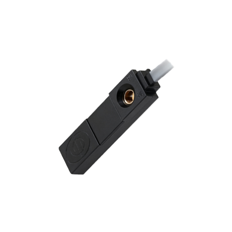
Electrical Noise and Electromagnetic Interference (EMI)
One of the most prevalent causes of a proximity sensor lighting up erroneously is electrical noise. Industrial environments are rife with sources of electromagnetic interference (EMI), such as variable frequency drives (VFDs), large motors, welding equipment, and high-current switching circuits. This interference can induce stray voltages in the sensor's output circuit or its signal lines, tricking the sensor into activating. For DC sensors, this is particularly common. The sensor's internal switching element, often a transistor, can be triggered by these voltage spikes, causing the output to turn on and the indicator LED to light. Shielding, proper grounding, and the use of filters or ferrite cores on cables are standard countermeasures to mitigate EMI.
Sensor Wiring and Ground Loop Issues
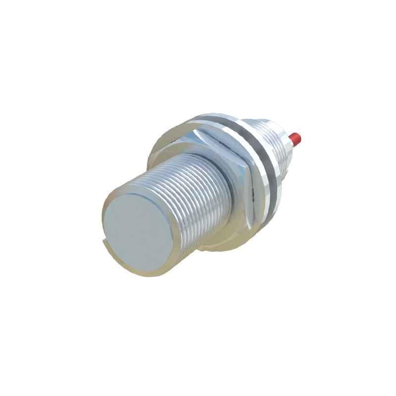
Incorrect wiring is a frequent culprit. For a standard 3-wire DC sensor, connecting the brown wire (typically +V) and blue wire (typically 0V or common) correctly to the power supply is essential. However, problems arise with the load connection. If the load (e.g., a PLC input) is connected between the sensor's output (black wire) and the positive supply, instead of between the output and the common/negative, it can cause unexpected behavior. Furthermore, ground loops—created when there are multiple paths to ground with potential differences—can introduce circulating currents. These currents can flow through the sensor's circuitry, leading to false triggering. Ensuring a single-point ground and verifying wiring against the manufacturer's datasheet are crucial steps.
Power Supply Problems and Voltage Fluctuations
The stability and quality of the power supply directly impact sensor performance. Voltage spikes, sags, or ripple on the DC supply line can cause unstable operation. A sensor might momentarily lose power or receive a surge that latches its output in an active state. Additionally, if the sensor's operating voltage range is, for instance, 10-30V DC, operating it at the very lower limit might make it susceptible to noise, causing false activation. Using a regulated, dedicated power supply for sensitive sensors and checking for stable voltage within the sensor's specified range are recommended practices. Transient voltage suppressors may also be necessary in areas with unstable power.
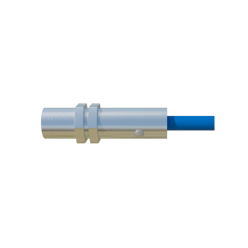
Environmental Contaminants and Physical Damage
The operating environment plays a significant role. Proximity sensors, especially inductive types, can be affected by metallic dust, chips, or conductive debris accumulating on the sensing face. This buildup can effectively "short" the sensing field, causing the sensor to detect its own face as a target. For capacitive sensors, moisture, oil, or dust adhering to the face can alter the dielectric constant and cause false triggering. Physical damage to the sensor housing or cable can expose internal components to moisture or cause short circuits. Regular cleaning of the sensor face using appropriate methods and inspecting for physical integrity are essential maintenance tasks.
Sensor Type and Technology Mismatch
Choosing the wrong sensor for the application can lead to persistent issues. Using a standard inductive sensor to detect a non-ferrous metal like aluminum or copper may require a reduced sensing range. If the installation does not account for this reduction, background metal (like the machine frame) might fall within the effective, albeit reduced, sensing range, causing constant activation. Similarly, capacitive sensors can be triggered by changes in humidity or the proximity of an operator's hand if not properly adjusted. Ultrasonic and photoelectric sensors have their own sets of challenges, such as sensing reflective backgrounds or airborne particles. Always verify the sensor's technology and specifications against the actual target and environment.
Internal Component Failure and Diagnostics
Finally, internal electronic failure can cause a sensor to latch in the "on" state. A failed output transistor, damaged oscillator circuit (in inductive sensors), or a fault in the application-specific integrated circuit (ASIC) can result in a permanent active output. Most modern proximity sensors have a built-in LED indicator that shows