Understanding Proximity Sensor Fundamentals
Proximity sensors are indispensable components in modern industrial automation, providing non-contact detection of metallic or other target objects. Their operation relies on generating an electromagnetic field or beam of radiation. When a target enters this field, it causes a change in the signal, which the sensor detects and converts into an electrical output. This non-contact nature eliminates mechanical wear and tear, ensuring high reliability and long service life in demanding environments. The core types include inductive sensors for metals, capacitive sensors for both metallic and non-metallic materials, and photoelectric sensors using light beams. Each type has specific wiring requirements that must be meticulously followed to ensure proper functionality and system safety. Understanding the basic operating principle is the first step before examining any wiring diagram, as it clarifies why specific connections are necessary for power, output signals, and protective circuits.
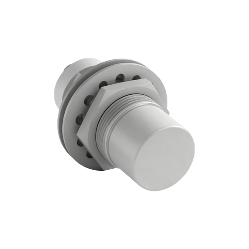
Key Components in a Standard Wiring Diagram
A standard proximity sensor wiring diagram typically illustrates several critical components. The central element is the sensor itself, often depicted with its housing and sensing face. The diagram will clearly show the cable or connector with individual wires color-coded according to international standards, such as brown for positive DC supply (+V), blue for negative DC supply (0V), and black for the switched output signal. For AC sensors, brown typically represents Line (L) and blue represents Neutral (N). Protective devices like surge suppressors or flyback diodes might be included, especially for inductive loads like relays or solenoids, to protect the sensor's solid-state output from voltage spikes. The diagram also shows the power source, whether it's 12-24V DC or 90-250V AC, and the load device being controlled, such as a programmable logic controller (PLC) input, a relay coil, or a pilot lamp. Labels for terminal numbers (e.g., 1, 2, 3, 4) or wire functions are always present for unambiguous connection.
Wiring for 3-Wire DC Inductive Proximity Sensors
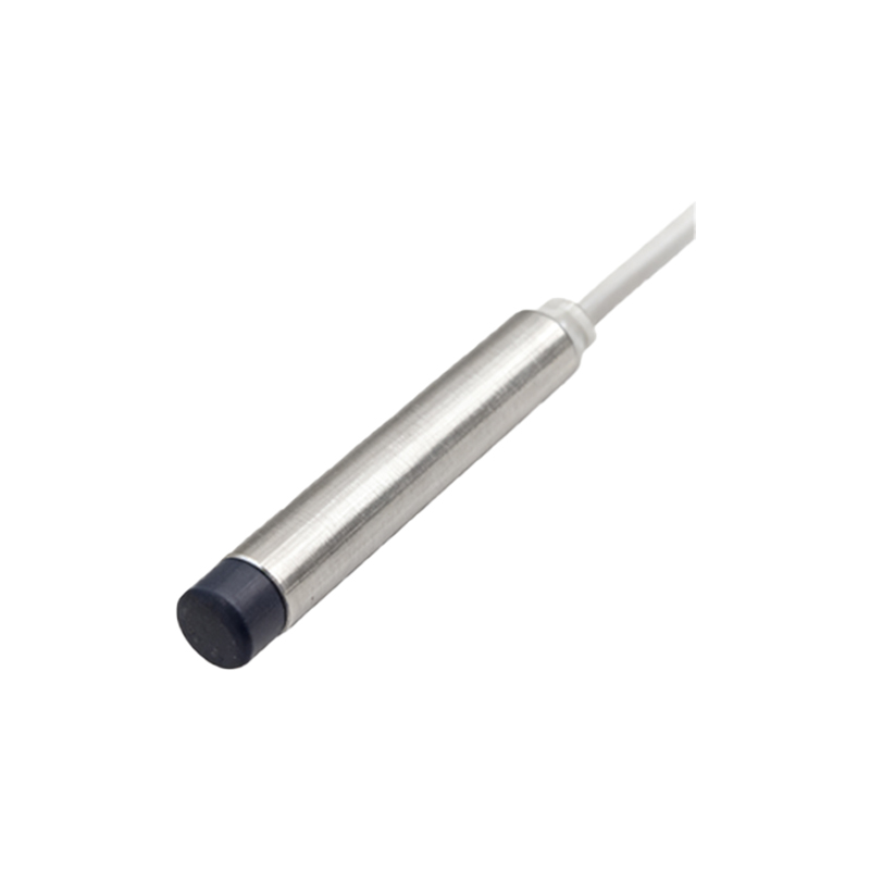
The 3-wire DC sensor is the most common configuration in industrial settings. The wiring diagram for this type is fundamental knowledge. The brown wire connects to the positive terminal of the DC power supply. The blue wire connects to the negative terminal or common (0V). The third wire, usually black, is the output signal. There are two output types: NPN (sinking) and PNP (sourcing). An NPN sensor diagram shows the black wire (output) connected to the load, and the other side of the load connected to the positive supply (+V). When activated, the NPN sensor sinks current to 0V, completing the circuit. Conversely, a PNP sensor diagram shows the black wire (output) connected to the load, with the other side of the load connected to 0V. When activated, the PNP sensor sources current from the positive supply. The wiring diagram must match the sensor's specified output type to interface correctly with the control system. A clear diagram will also indicate the required polarity and voltage range.
Interpreting 2-Wire AC/DC Sensor Connections
Two-wire proximity sensors are simpler to wire but require careful consideration of the load. In a wiring diagram for a 2-wire AC sensor, the two wires are connected in series with the AC power source and the load. There is no polarity. The sensor acts as a switch, allowing current to flow through itself and the load when a target is detected. The diagram is crucial here because it specifies the minimum and maximum load current (e.g., 5mA to 200mA) required for reliable operation; the sensor needs a small "leakage" current to function even when off. If the load draws less than the minimum current, the sensor may not turn off completely, causing a malfunction. Similarly, 2-wire DC sensors have polarity, with one wire to positive and the other to the load, which then connects to negative. Diagrams for these models always emphasize the current window and the voltage drop across the sensor when conducting.
Practical Wiring Diagram for a Shielded vs. Unshielded Sensor
Wiring diagrams often specify if the sensor is shielded (flush-mountable) or unshielded (non-flush mountable). This has a direct impact on installation. A diagram for a shielded inductive sensor shows that it can be mounted flush in metal without affecting its sensing range, as its magnetic field is concentrated at the front. The wiring connections remain the same, but the diagram may include a note about the permissible surround metal. An unshielded sensor diagram typically warns against flush mounting in metal, as its extended lateral magnetic field would be disturbed, causing false triggers or reduced range.