Understanding Proximity Sensor Basics
Proximity sensors are essential components in industrial automation, detecting the presence or absence of an object without physical contact. They operate based on electromagnetic fields, capacitive changes, or ultrasonic signals, with inductive and capacitive types being most common. Inductive sensors detect metallic objects, while capacitive sensors can detect both metallic and non-metallic materials. Proper wiring is critical to ensure reliable operation, safety, and longevity of these sensors in harsh industrial environments. Before proceeding with any wiring, always refer to the manufacturer's datasheet for specific voltage, current, and connection details to avoid damage or malfunction.
Key Components and Terminal Identification
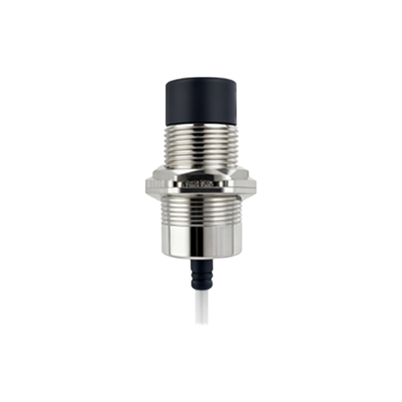
A standard three-wire proximity sensor typically includes three terminals: brown (positive/+V), blue (negative/0V or common), and black (output signal). Some sensors may have additional wires for diagnostic functions or complementary outputs. The brown wire connects to the positive supply voltage, usually ranging from 10-30V DC for DC sensors. The blue wire is connected to the power supply's negative terminal or ground. The black wire carries the output signal, which can be either normally open (NO) or normally closed (NC), switching the load when an object is detected. Always verify terminal markings, as colors can vary by region or manufacturer.
DC Three-Wire Sensor Wiring Procedure
For a DC three-wire inductive proximity sensor, begin by ensuring the power supply is disconnected. Connect the brown wire to the positive terminal of your DC power source, typically +24V DC in industrial settings. Connect the blue wire to the negative terminal of the power source. The black output wire is then connected to the input of your controller, such as a PLC input module or relay. If the sensor is NPN type, the black wire will switch the negative side; for PNP types, it switches the positive side. A load, like a relay coil or PLC input, is placed between the output and the opposite supply polarity. Always use shielded cables in electrically noisy environments and ground the shield properly.
Wiring Two-Wire AC/DC Sensors
Two-wire sensors are simpler but require careful consideration of voltage drop and leakage current. These sensors have only two terminals, connecting in series with the load and power supply. They can operate on both AC and DC voltages. When wiring, one terminal connects to the power source, and the other connects to the load, which then returns to the opposite power supply terminal. Ensure the sensor's voltage rating matches the supply, and the load current falls within the sensor's specified range. Excessive load current can damage the sensor, while insufficient current may prevent it from switching properly. A protective fuse or circuit breaker is recommended in the supply line.
Connecting to Programmable Logic Controllers (PLCs)
Integrating proximity sensors with PLCs is common in automation systems. For a three-wire DC sensor connected to a PLC digital input, first identify whether the PLC input is sinking (NPN compatible) or sourcing (PNP compatible). For a PNP sensor, connect the brown wire to +24V DC, blue to 0V DC, and the black wire to the PLC input terminal. The PLC input's common terminal should be connected to 0V DC. For an NPN sensor, the black wire connects to the PLC input, and the input common connects to +24V DC. Always include a protective diode or surge suppressor if the sensor controls inductive loads to prevent voltage spikes from damaging the PLC.
Wiring Considerations for Multiple Sensors
When installing multiple proximity sensors, avoid interference by maintaining adequate spacing between units, typically at least twice the sensor's diameter. Use separate conduits or shielded cables for power and signal lines to minimize cross-talk. For sensors sharing a common power supply, ensure the supply has sufficient current capacity and consider using individual fuses for each sensor. Group sensors with similar characteristics together, and label all wires clearly at both ends to simplify troubleshooting. Ground all sensor housings to the control panel's ground bus to enhance noise immunity and safety.
Common Mistakes and Troubleshooting Tips
Incorrect wiring is a frequent cause of sensor failure. Avoid connecting the output wire directly to the power supply, which can cause a short circuit. Ensure polarity is correct for DC sensors; reversing brown and blue wires may permanently damage the device. If a sensor fails to detect objects, check the sensing distance and ensure the target material is compatible. Use a multimeter to verify voltage at the sensor terminals and output switching. For intermittent operation, inspect for loose connections, damaged cables, or environmental factors like temperature extremes or contamination. Regularly clean the sensor