Introduction to Capacitive Sensing Technology
Capacitive proximity sensors operate on a fundamental principle of physics: the ability to store an electrical charge. At their core, these sensors function by generating an electrostatic field from a sensing electrode, typically housed within the sensor face. When any object enters this electrostatic field, it causes a measurable change in the capacitance of the system. This change is detected by the sensor's internal oscillator circuit. Unlike inductive sensors that only detect metals, capacitive sensors can detect a vast array of materials, including liquids, powders, granules, plastics, and wood, provided the material has a dielectric constant different from air. This versatility stems from the fact that all materials influence an electric field to some degree, making capacitive sensing a powerful tool for non-contact detection across numerous industrial applications.
Core Operating Principles and Internal Architecture
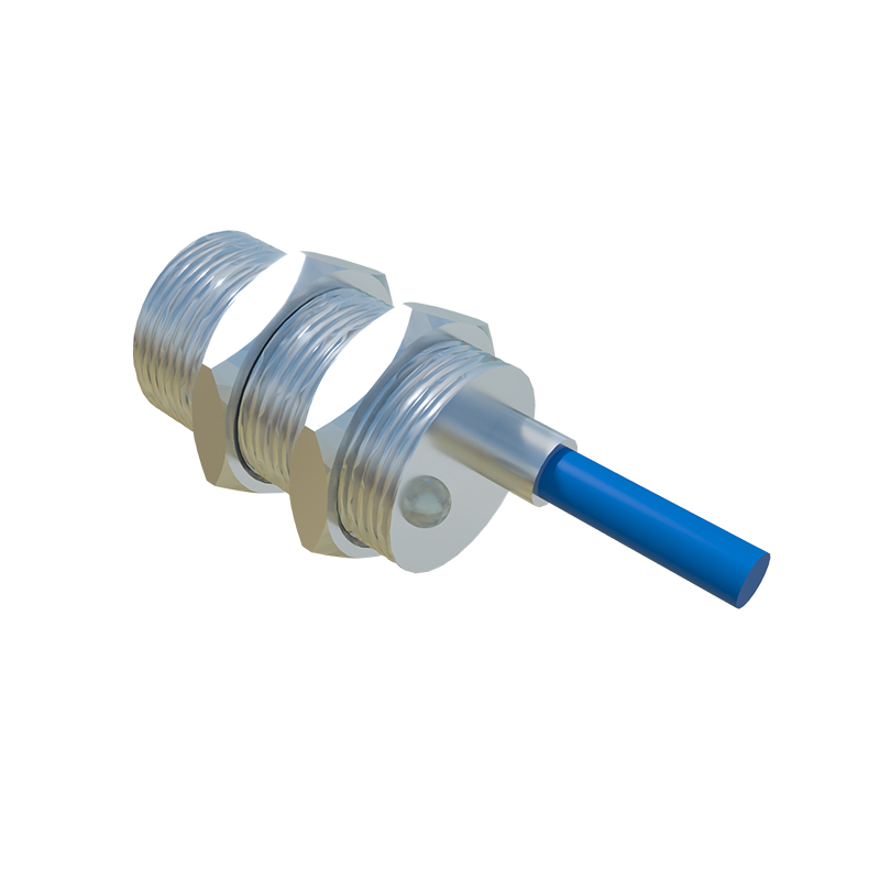
The internal architecture of a capacitive proximity sensor is elegantly engineered for sensitivity and stability. The primary components include a high-frequency oscillator, a sensing electrode (which forms one plate of a capacitor, with the target object acting as the other plate), a signal conditioner, and an output switching circuit. The oscillator generates a constant electrostatic field. As a target object approaches, the capacitance between the electrode and the object increases. This increase in capacitance alters the amplitude of the oscillator's signal. The signal conditioner processes this change, and once it surpasses a predefined threshold—the sensing distance—it triggers the output circuit to switch state. Many sensors feature a potentiometer for sensitivity adjustment, allowing engineers to fine-tune the sensing distance and compensate for environmental factors or to ignore certain materials, such as a container wall to sense the liquid level inside.
Key Performance Characteristics and Specifications
Understanding the datasheet parameters is crucial for correct sensor selection. The rated operating distance (Sn) is the nominal sensing range under standardized conditions. It is vital to note that this distance can vary based on the target material's size, shape, and dielectric constant. The hysteresis is the difference between the switch-on and switch-off points, providing stability to prevent output chatter when a target is at the sensing boundary. Response frequency indicates how quickly the sensor can detect objects per second, a critical factor in high-speed applications. Other essential specifications include the operating voltage range (e.g., 10-30V DC), output type (PNP/NPN, NO/NC), current rating, and protection ratings like IP67 for dust and water ingress. Temperature drift and dielectric constant of the target material are also primary influencers on reliable performance.
Application-Specific Configurations and Mounting Guidelines
Correct installation is paramount for optimal performance. Capacitive sensors can be susceptible to false triggering from unwanted influences. Flush-mountable (shielded) sensors have a focused field that extends only from the front face, making them ideal for embedded mounting in metal tanks or hoppers without the metal interfering. Non-flush (unshielded) sensors have a larger, lateral sensing field and offer a longer range but require a non-metallic surrounding area. A critical mounting rule is to maintain a clearance zone around the sensor, free from conductive materials, as specified by the manufacturer. For liquid level detection, sensors are often mounted externally on non-metallic container walls. Proper grounding of both the sensor and the machinery is essential to minimize electrical noise interference, which can adversely affect sensitivity.
Calibration, Troubleshooting, and Common Challenges
Effective calibration involves using the sensitivity adjustment potentiometer. The procedure typically requires bringing the target object to the desired sensing position and adjusting the pot until the output indicator LED switches, then backing off slightly to ensure a stable operating point. Common troubleshooting issues include reduced sensing range, which may be caused by sensor contamination (dust, moisture), incorrect power supply, or a degraded sensing face. False triggering often results from environmental factors like high humidity, conductive dust buildup, or interference from adjacent sensors or power lines. Engineers should systematically verify power, check for environmental contaminants, ensure the target is within the effective sensing range for its material, and inspect for physical damage. Regular maintenance, including cleaning the sensing face with appropriate solvents, is recommended for sustained reliability.
Advanced Considerations and Industry Trends
Modern capacitive sensors incorporate advanced features for smarter automation. Analog output versions provide a continuous voltage or current signal proportional to the distance to the target, enabling precise level monitoring or thickness measurement. Sensors with IO-Link capability offer digital communication for parameter setting, process data reporting, and advanced diagnostics directly to the PLC, facilitating predictive maintenance and Industry 4.0 integration. Another trend is the development of extremely compact form factors for space-constrained applications and sensors designed with robust housing materials to withstand aggressive cleaning chemicals in food and pharmaceutical industries. Understanding these advancements allows engineers to design more intelligent,