Understanding the R11S Proximity Sensor
The R11S inductive proximity sensor is a widely used component in industrial automation for detecting metallic objects without physical contact. Its operation relies on generating an electromagnetic field. When a metal target enters this field, it causes a change in the sensor's oscillation amplitude, triggering a switching output. Proper calibration is not merely a recommendation but a critical procedure to ensure the sensor operates within its specified sensing range, maintains repeatability, and provides reliable signals to the PLC or control system. An uncalibrated sensor can lead to false triggers, missed detections, and ultimately, production line downtime or quality issues.
Pre-Calibration Safety and Preparation
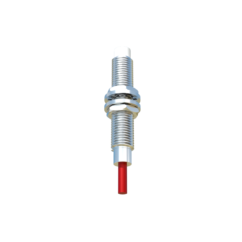
Before initiating any calibration procedure, adhere to strict safety protocols. De-energize the electrical circuit controlling the sensor and lock out/tag out (LOTO) the power source to prevent accidental activation. Gather the necessary tools: the sensor's datasheet, a set of certified gauge blocks or test targets made of the correct material (typically mild steel), a stable mounting fixture, a digital multimeter, and the required hand tools. Ensure the sensor is installed correctly according to the manufacturer's specifications regarding mounting, flush or non-flush conditions, and environmental factors like temperature and presence of contaminants. Verify the electrical connections are secure and the wiring matches the sensor's PNP or NPN configuration and voltage rating.
Step-by-Step Calibration Procedure
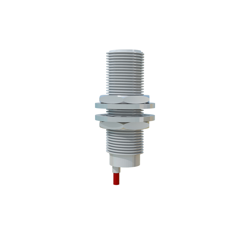
Begin by powering the sensor with its specified voltage, typically 10-30V DC. Using the designated test target, slowly bring it axially toward the active face of the sensor. Observe the sensor's output indicator LED and simultaneously monitor the output signal with a multimeter set to measure DC voltage. The point at which the LED illuminates and the output voltage switches (e.g., from 0V to ~24V for a PNP sensor) is the "switch-on point." Mark this distance. Continue moving the target closer until it is at the rated sensing distance (Sn), then slowly retract it. The point where the LED extinguishes and the output switches off is the "switch-off point." The difference between the switch-on and switch-off points is the hysteresis, which is a designed feature to prevent output chatter. The key calibration goal is to confirm that the actual switch-on point occurs within the tolerances specified in the datasheet for the rated sensing distance. If using an adjustable (potentiometer) version of the R11S, make fine adjustments at this stage to set the precise sensing distance required for the application.
Verification and Performance Testing
After the initial calibration, perform a series of verification tests to ensure stability and repeatability. Conduct at least ten approach-and-retract cycles with the target, recording the switch-on and switch-off distances each time. The variation should be minimal, confirming good repeatability. Test with the actual application target if it differs from the calibration target, noting any difference in sensing distance due to material factors (the correction factor for different metals is provided in the datasheet). Expose the sensor to expected operational vibrations or temperature variations if possible, and re-check the switching points. Finally, integrate the sensor back into the control system and run a full functional test of the machine or process cycle to validate that the sensor triggers the programmed sequence correctly and consistently under real operating conditions.
Troubleshooting Common Calibration Issues
Several issues may arise during or after calibration. If the sensor fails to switch, double-check the power supply polarity and voltage, and confirm the target material and size meet minimum requirements. Erratic switching or reduced sensing range can be caused by electrical noise; ensure shielded cables are used and grounded properly at the controller end, and keep sensor wiring separate from high-voltage AC lines. If the sensing distance drifts over time, it may indicate a failing component, environmental interference like metallic dust buildup on the face, or excessive temperature beyond the sensor's rating. Always consult the diagnostic indicators on the sensor itself and cross-reference symptoms with the troubleshooting chart in the product manual before considering replacement.
Maintaining Calibration Long-Term
Calibration is not a one-time event. Establish a preventive maintenance schedule to periodically re-check the R11S sensor's performance. The frequency depends on the operating environment's harshness—high cycle rates, extreme temperatures, or exposure to coolants and metal chips necessitate more frequent checks. During maintenance, visually inspect the sensor face for damage or contamination and clean it with a soft cloth if needed. Keep a log of all calibration dates, measured values, and any adjustments made. This historical data is invaluable for predicting sensor lifespan and diagnosing intermittent system