Core Components and Operating Principle
Inductive proximity sensors are fundamental non-contact detection devices widely used in industrial automation. Their operation relies on the principle of electromagnetic induction. At the heart of the sensor lies a coil wound around a ferrite core, which forms part of an oscillator circuit. When an alternating current is applied, the coil generates a high-frequency electromagnetic field that radiates from the active face of the sensor. This field is typically confined to a short range. When a metallic target enters this detection field, eddy currents are induced on the surface of the target. These eddy currents draw energy from the oscillator, resulting in a measurable change in the oscillation amplitude. This amplitude reduction is precisely detected by a subsequent evaluation circuit, which triggers a solid-state output switch. The entire process is contactless, wear-free, and exceptionally reliable for detecting ferrous and non-ferrous metals, albeit with different sensing distances.
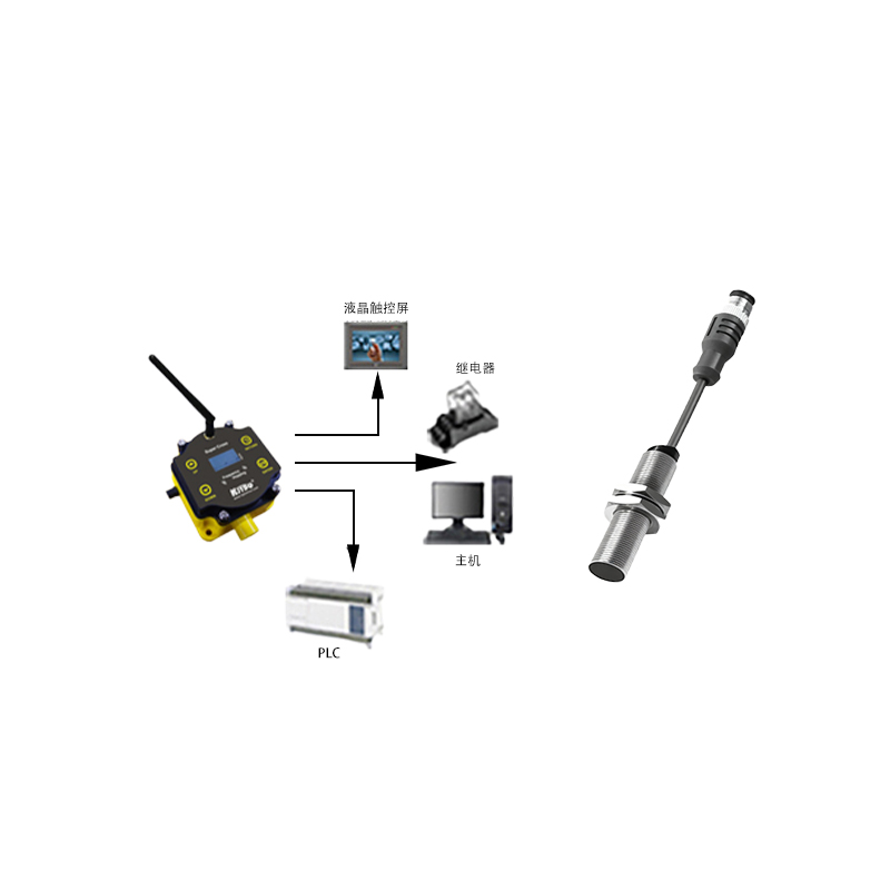
Detailed Internal Architecture
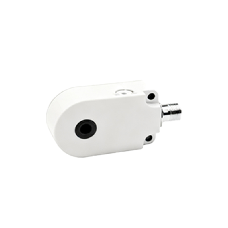
The internal structure of a standard inductive proximity sensor is a sophisticated assembly of several key modules housed within a robust casing, typically made of nickel-plated brass, stainless steel, or PBT plastic. The front section contains the sensing face and the ferrite core with the wound coil. Directly behind the oscillator coil is the core oscillator circuit, often implemented on a printed circuit board (PCB). This high-frequency oscillator, operating in the range of several hundred kHz, is responsible for generating the electromagnetic field. The signal from the oscillator is fed into a demodulator and amplifier stage. This circuit converts the change in oscillation amplitude into a clean DC signal. Following this, a Schmitt trigger or a similar comparator circuit provides hysteresis, ensuring a clean, bounce-free switching signal even when a target is vibrating or moving slowly at the detection boundary.
Output Stage and Housing Design
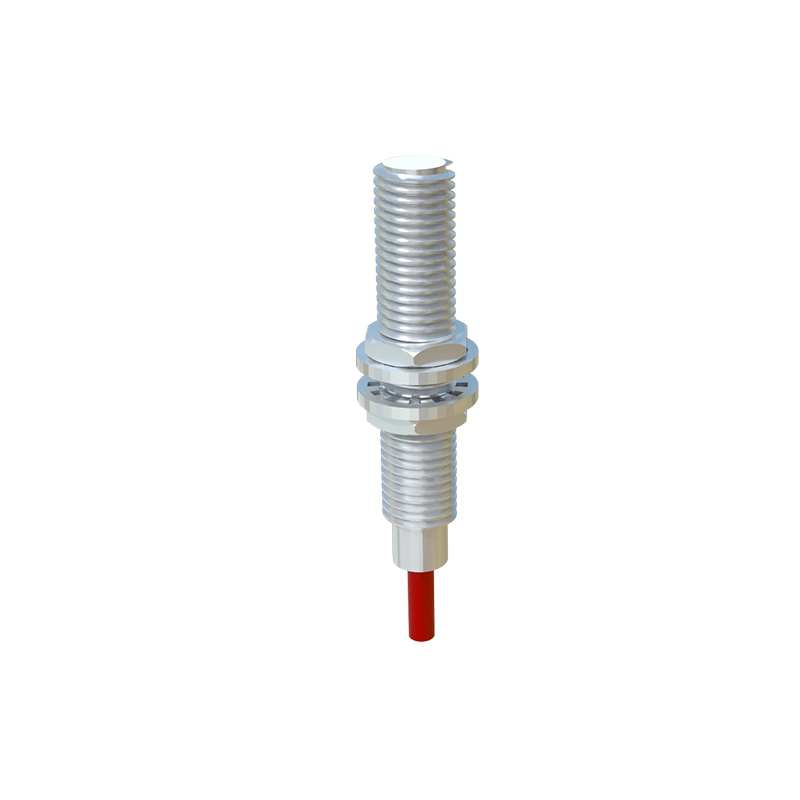
The processed signal activates the output stage. Modern sensors predominantly use solid-state outputs, either as NPN (sinking) or PNP (sourcing) transistors, or in a configurable NO/NC (Normally Open/Normally Closed) format. Some heavy-duty models may incorporate relay outputs. The output transistors are protected against short-circuits, overloads, and reverse polarity. All electronic components are potted with a resilient epoxy resin compound. This potting material provides critical protection against vibration, mechanical shock, and the ingress of contaminants like dust, coolants, and oils, ensuring compliance with high Ingress Protection (IP) ratings such as IP67 or IP69K. The housing geometry is designed for easy installation, often featuring threaded barrels (e.g., M8, M12, M18, M30) or rectangular block styles with standardized mounting holes.
Shielded vs. Unshielded (Flush Mountable) Designs
A critical structural distinction lies in the design of the magnetic field, leading to two primary types: shielded (flush mountable) and unshielded (non-flush mountable). Shielded sensors have a metal ring (usually ferrous) surrounding the sensing coil. This ring confines the electromagnetic field radially, allowing the sensor to be installed flush in a metal bracket without the bracket itself being detected. This design offers a shorter sensing range but enables versatile, space-saving mounting. Unshielded sensors lack this surrounding metal shield. Their electromagnetic field projects both forward and radially, resulting in a longer sensing distance. However, they require a clearance zone free of surrounding metal to prevent false triggering, as adjacent metal can influence the sensing field. The choice between shielded and unshielded is a key application consideration.
Factors Influencing Sensing Performance
The operational performance and effective sensing range (Sn) are not solely determined by the internal electronics but are significantly influenced by structural and material factors. The size and geometry of the sensing coil directly affect the range and shape of the detection field. The oscillator's frequency and stability are crucial for consistent performance. Furthermore, the target material plays a major role. For a standard mild steel target, the rated sensing distance is defined. For other metals, a reduction factor is applied; for instance, stainless steel may be detected at 0.7 to 0.9 times the rated distance, while copper or aluminum may be as low as 0.3 to 0.4 times. The target size must generally be equal to or larger than the sensor's sensing face diameter for the full rated range. Environmental factors like extreme temperatures can also affect the coil's inductance and the circuit's behavior, which high-quality sensors compensate for internally.