Introduction to Normally Open Proximity Sensors
A Normally Open (NO) proximity sensor operating at 220V AC is a fundamental component in modern industrial automation and control systems. Unlike mechanical limit switches, these non-contact sensors detect the presence or absence of a metallic target without physical contact, offering superior reliability and longevity. The "Normally Open" designation indicates that the sensor's output circuit is open (non-conducting) when no target is within its sensing range. Upon detecting a valid target, the internal switching element closes, allowing current to flow through the output terminals, typically to control a relay, contactor, or PLC input. The 220V AC rating specifies the operational voltage of the sensor's power supply and output switching capability, making it directly compatible with common industrial power networks in many regions, eliminating the need for additional control voltage transformers.
Operating Principle and Key Technologies

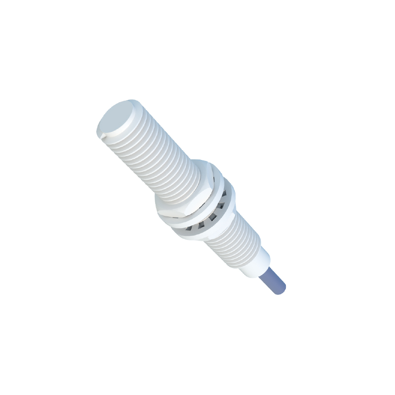
The core technology behind a 220V AC NO proximity sensor is typically inductive sensing. The sensor contains an oscillator circuit that generates a high-frequency electromagnetic field from its active face. When a ferrous or non-ferrous metal object enters this field, eddy currents are induced in the target. This causes a change in the oscillation amplitude or frequency within the sensor. A subsequent evaluation circuit detects this change and triggers a solid-state switch (like a Triac) or a relay to change state. For a NO configuration, this action closes the switch, completing the 220V AC circuit. Key specifications include sensing distance, which is standardized (e.g., Sn) and often reduced for non-ferrous metals, repeat accuracy, and switching frequency. The robust housing, usually made of brass, stainless steel, or PBT plastic, provides protection against chips, coolants, and environmental factors, commonly rated IP67 or higher.
Wiring and Electrical Integration
Correct wiring is critical for the safe and reliable operation of a 220V AC NO proximity sensor. Standard three-wire sensors have Brown (L+ or Live), Blue (N or Neutral), and Black (Output) wires. The Brown wire connects to the 220V AC phase line, and the Blue wire connects to the neutral. The Black output wire carries the switched 220V AC load. A two-wire AC sensor simplifies wiring by connecting in series with the load but requires a minimum load current to function correctly. It is imperative to consult the manufacturer's datasheet for specific wiring diagrams. Essential integration practices include using a separate fuse for protection, ensuring proper grounding if applicable, and considering the use of a surge suppressor or RC network when switching inductive loads like contactor coils to protect the sensor's internal electronics from voltage spikes.
Application Scenarios in Industrial Systems
The 220V AC NO proximity sensor finds extensive use across various industries due to its direct high-voltage switching capability. Common applications include position detection in machine tools, such as verifying the end-of-travel of a slide or the presence of a workpiece on a conveyor. They are ideal for controlling cabinet door interlocks for safety, where the door's closure is detected to enable machine operation. In material handling, they count metallic objects on production lines. Their ruggedness makes them suitable for harsh environments like stamping presses or foundries. The NO configuration is particularly useful for initiating an action upon detection, such as starting a motor when a part arrives or stopping a process when a bin is full, by directly energizing a 220V AC control circuit.
Selection Criteria and Best Practices
Selecting the right 220V AC NO sensor requires careful consideration of several parameters. First, determine the required sensing distance and ensure it accounts for any installation tolerances. The target material (steel, aluminum, copper) significantly affects the effective range. The housing material and shape (cylindrical, rectangular, ring-shaped) must suit the mechanical and environmental constraints. Electrical characteristics are paramount: ensure the load current of the connected device (e.g., relay coil) does not exceed the sensor's maximum switching current, and the voltage is within the specified range (e.g., 90-250V AC). For NO outputs, verify the leakage current when "off" is acceptable for the load. Best practices include maintaining a clean sensing face, allowing a 10-20% margin on the rated sensing distance, and testing the installation with the actual target material under real operating conditions.
Troubleshooting Common Issues
Even robust sensors can encounter issues. A common problem is failure to detect the target. This can be caused by incorrect installation distance, a dirty sensing face, or an unsuitable target material (e.g., trying to sense non-metallic objects with an inductive sensor). Electrical faults include no output signal