Introduction to Inductive Proximity Sensors
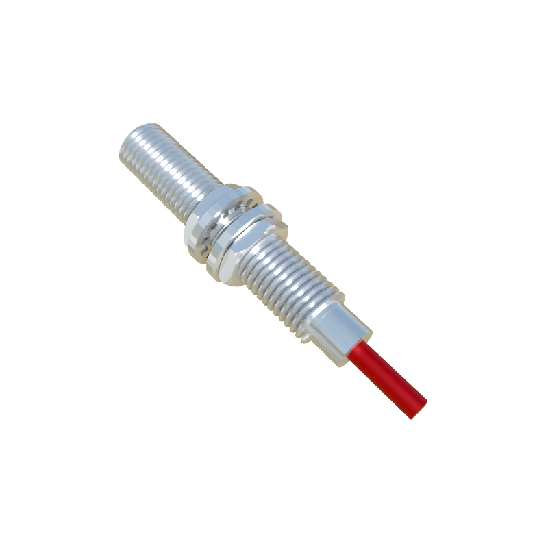
Inductive proximity sensors are fundamental components in industrial automation, widely used for non-contact detection of metallic objects. These sensors operate on the principle of electromagnetic induction, generating an oscillating electromagnetic field from a coil. When a metallic target enters this field, eddy currents are induced in the target, causing a change in the sensor's oscillation amplitude. This alteration is detected by the internal circuitry, which then triggers an output signal. The schematic diagram of an inductive proximity sensor provides a detailed view of its electronic architecture, illustrating how various components interact to achieve reliable object detection. Understanding this schematic is crucial for engineers involved in sensor selection, integration, and troubleshooting within complex control systems.
Core Components in the Schematic
The schematic diagram typically reveals several key sections. At its heart is the oscillator circuit, usually built around a coil (L) and a capacitor (C) forming an LC tank circuit. This circuit generates a high-frequency electromagnetic field. The demodulator circuit follows, responsible for converting the amplitude changes in the oscillation into a DC voltage signal. A Schmitt trigger or comparator stage then processes this DC signal, comparing it to a predefined threshold to produce a clean, digital output (e.g., PNP or NPN transistor switch). Additionally, the schematic includes power supply regulation and protection components, such as diodes for reverse polarity protection and resistors for current limiting, ensuring stable operation in harsh industrial environments.
Analyzing the Oscillator and Demodulator
The oscillator section is critical for defining the sensor's sensing range and frequency. In the schematic, the LC tank's resonant frequency is determined by the values of the inductor (the sensing coil) and the capacitor. When a metal object approaches, the eddy currents absorb energy, increasing the losses in the tank circuit ("damping" the oscillation). This energy loss leads to a decrease in the oscillation amplitude. The demodulator, often a diode and RC filter network, rectifies and smoothes this amplitude-modulated signal. The resulting DC voltage level is directly proportional to the damping effect, thus correlating to the target's proximity. This stage transforms the physical phenomenon of induction into an electrical signal suitable for further processing.
Output Stage and Switching Logic
The processed signal from the demodulator is fed into a threshold detection circuit. This is commonly a Schmitt trigger, which provides hysteresis to prevent output chatter when the target is at the borderline of the sensing distance. Once the signal crosses the "ON" threshold, the output stage activates. The output stage is typically a solid-state switch, either a PNP (sourcing) or NPN (sinking) transistor configuration, as clearly shown in the schematic with its associated base, emitter, and collector connections. This switch controls the flow of current to the load (e.g., a PLC input, relay, or indicator lamp). The schematic also details the connection of the output to the external load, including the necessary wiring for the power supply (Vcc), output (OUT), and common ground (GND) terminals.
Practical Considerations from the Schematic
A thorough analysis of the schematic diagram offers practical insights for application engineers. It clarifies the sensor's wiring requirements, such as whether it is a 2-wire, 3-wire, or 4-wire device. The presence of protection components like varistors or TVS diodes indicates the sensor's robustness against voltage spikes and electromagnetic interference (EMI). Furthermore, the schematic can reveal details about the sensing face's design and the coil's geometry, which influence the sensor's field shape and sensing characteristics. By studying the schematic, engineers can better understand factors like residual current (for 2-wire AC sensors), leakage current, and short-circuit protection, all vital for designing safe and reliable control panels and machinery.
Conclusion and Application Insights
In summary, the schematic diagram of an inductive proximity sensor is a blueprint that deciphers its operational intelligence. From the generation of the electromagnetic field to the final switching action, each component plays a defined role. Mastery of this schematic empowers engineers to select the right sensor for specific metals (ferrous vs. non-ferrous), optimize installation to avoid mutual interference between multiple sensors, and perform effective diagnostics when malfunctions occur. As automation systems demand higher precision and reliability, a deep, schematic-level understanding of these ubiquitous sensors remains an invaluable asset for any electrical or control engineer.