Understanding Proximity Sensor Fundamentals
Proximity sensors are pivotal components in modern industrial automation, detecting the presence or absence of objects without physical contact. These devices operate on various principles, including inductive, capacitive, ultrasonic, and photoelectric technologies. Inductive sensors are ideal for metallic targets, while capacitive types can detect non-metallic materials. Ultrasonic sensors use sound waves for distance measurement, and photoelectric sensors rely on light beams. Selecting the appropriate sensor type is the first critical step for any installation team, as it directly impacts system reliability and performance. A thorough understanding of these fundamentals ensures that the team can make informed decisions during the planning and execution phases.
Pre-Installation Planning and Site Assessment
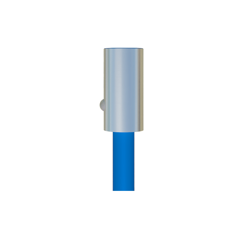
Before any physical work begins, a comprehensive site assessment is essential. The installation team must evaluate environmental factors such as temperature extremes, humidity, dust, vibration, and potential exposure to chemicals or corrosive substances. Electrical characteristics of the location, including voltage supply stability and potential electromagnetic interference, must also be analyzed. This phase involves reviewing mechanical drawings, identifying optimal mounting locations, and ensuring adequate clearance for sensor operation and maintenance. Detailed planning minimizes costly rework and prevents operational failures post-installation. Creating a checklist based on the sensor manufacturer's specifications and the client's operational requirements is a standard best practice.
Mounting and Mechanical Installation Procedures
Correct mechanical mounting is crucial for sensor accuracy and longevity. The team must follow precise alignment guidelines to ensure the sensor face is perpendicular to the target's approach path. Mounting brackets should be rigid and vibration-resistant, typically made from materials like stainless steel or anodized aluminum. For cylindrical sensors, proper tightening torque must be applied to avoid damaging the housing. Adjustable mounting systems are often employed to fine-tune position after installation. It is vital to maintain the specified sensing distance and consider factors like target material, size, and approach speed. Protective measures, such as installing metal guards for sensors in high-traffic areas, prevent physical damage from collisions or debris.
Electrical Wiring and Connection Standards
Electrical installation demands strict adherence to safety codes and manufacturer wiring diagrams. Teams must differentiate between sourcing (PNP) and sinking (NNP) configurations and connect them correctly to the programmable logic controller (PLC) or other control systems. Shielded cables are recommended for long runs or electrically noisy environments to prevent signal degradation. All connections should be secure, using appropriate wire gauges and corrosion-resistant terminals. Implementing proper grounding techniques is non-negotiable to avoid ground loops and ensure stable operation. Labeling all wires and documenting the wiring scheme facilitates future troubleshooting and maintenance. For hazardous locations, installations must comply with standards like ATEX or IECEx for explosive atmospheres.
Configuration, Calibration, and Testing Protocols
Once installed, sensors require precise configuration and calibration. Teams adjust parameters such as sensitivity, hysteresis, and response time to match application needs. For analog sensors, scaling the output signal (e.g., 4-20mA or 0-10V) to the control system is critical. Testing involves verifying the sensor's response with actual targets under normal operating conditions. Diagnostic tools, like LED indicators or proprietary software, help confirm optimal performance. Functional safety checks, including testing fail-safe modes and redundancy systems where applicable, are conducted. A formal test report documenting all settings and outcomes provides a valuable reference for the client and future service teams.
Commissioning and Integration with Control Systems
Commissioning integrates the sensor into the broader automation system. The team collaborates with control engineers to ensure seamless communication between the sensor and the PLC, robotic controller, or SCADA system. This phase includes verifying input signals in the control logic, setting up alarm thresholds, and programming appropriate responses for detected events. Simulation of production scenarios helps validate the entire setup before full-scale operation. Documentation of integration points, network addresses (for IO-Link or Ethernet-enabled sensors), and software configurations is essential for system transparency.
Ongoing Maintenance and Troubleshooting Strategies
Proactive maintenance extends sensor life and prevents unplanned downtime. Regular schedules should include cleaning lens or sensing faces, checking mounting integrity, and verifying electrical connections. Environmental seals should be inspected for wear. Troubleshooting common issues—like false triggering, reduced sensing range, or signal drift—often involves checking for environmental changes, accumulated debris, or power supply problems. Teams use systematic approaches, starting with visual inspections and progressing to electrical measurements with multimeters or oscilloscopes. Keeping a log of maintenance activities and failures aids in identifying recurring problems and predicting sensor lifespan.
Training and Safety Considerations for the Team
A skilled installation team is the backbone