Understanding the Core Components
Integrating a 3-wire proximity sensor with a Variable Frequency Drive (VFD) is a common task in industrial automation for applications like speed monitoring, positioning, or safety interlocks. A 3-wire DC sensor typically comprises a brown wire for positive DC supply, a blue wire for the common negative or 0V, and a black wire which is the switched output signal. The VFD, on the other hand, is equipped with digital inputs designed to accept control signals for functions like run/stop, speed reference, or fault reset. The successful interface hinges on correctly matching the sensor's output type (PNP or NPN) with the VFD input's electrical characteristics.
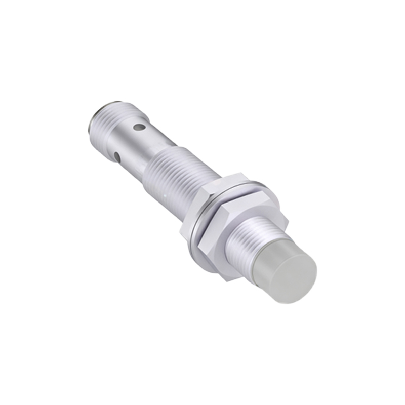
Identifying Sensor Output Type and VFD Input Compatibility
The first critical step is to determine whether your proximity sensor is PNP (sourcing) or NPN (sinking). A PNP sensor switches the positive voltage to its output black wire when activated. An NPN sensor switches the negative or 0V line. Most modern VFDs feature programmable digital inputs that can be configured as either sinking or sourcing, or are optically isolated, accepting a voltage signal relative to a common terminal. Consult the VFD manual to identify the specifications of its control terminals—typically labeled as common (COM), digital input 1 (DI1), etc.—and the acceptable voltage range, often 10-30V DC.
Wiring Configuration for a PNP Sensor
For a PNP proximity sensor, the wiring is relatively straightforward. Connect the sensor's brown wire to the positive DC power supply, usually +24V DC. Connect the sensor's blue wire to the negative or 0V of the same power supply. The sensor's black output wire is then connected to the designated digital input terminal on the VFD (e.g., DI1). The common (COM) terminal of the VFD's control circuit must be connected to the 0V of the DC power supply. This completes the circuit: when the sensor detects a target, +24V is supplied from the sensor's black wire to the VFD input, signaling a logic high or "on" state.
Wiring Configuration for an NPN Sensor
Wiring an NPN sensor requires a different approach. Connect the brown wire to +24V DC and the blue wire to 0V, as before. For the NPN type, the black output wire acts as a switched negative. This black wire should be connected to the VFD's digital input terminal. However, the VFD's common (COM) terminal must now be connected to the positive (+24V) of the DC power supply. In this configuration, when the sensor activates, it connects the VFD input terminal to 0V, pulling it low and signaling a logic low or "on" state to the VFD, which is typically configured to recognize this change.
Power Supply Considerations and Isolation
It is highly recommended to use a separate, regulated DC power supply for the sensor, rather than tapping power directly from the VFD's internal control supply. This prevents electrical noise generated by the VFD's high-power switching from interfering with the sensitive sensor signal, which could cause erratic operation. Ensure the power supply ground is properly bonded to the system ground. If the VFD input is optically isolated, it provides excellent noise immunity. Always verify that the voltage levels of the sensor output and the VFD input are compatible to prevent damage.
Configuring the VFD Parameters
After the physical wiring is complete, the VFD parameters must be programmed. Access the VFD's parameter menu to assign the function of the digital input you used. Common assignments include "Run Enable," "Multi-speed Select," or "External Fault." You may also need to set the logic for that input, such as defining whether a closed contact (signal present) means run or stop. For speed monitoring, the sensor signal might be routed to a high-speed counter input if available. Always perform a functional test by activating the sensor and observing the VFD's response on its display or via output relays.
Troubleshooting Common Interface Issues
If the system does not operate as expected, begin troubleshooting. Use a multimeter to confirm the sensor is receiving the correct supply voltage (e.g., 24V between brown and blue wires). Check for the presence of the output signal (either +24V for PNP or 0V for NPN) on the black wire when a target is present. Verify the wiring to the VFD terminal block