Understanding Proximity Sensor Fundamentals
Proximity sensors are critical components in modern industrial automation, detecting the presence or absence of an object without physical contact. Their operation hinges on generating an electromagnetic field or beam of radiation. When a target object enters this field, it causes a change in the sensor's oscillation or signal return. This change is converted into an electrical signal, which is then interpreted as a detection event. The core value output by these sensors, often a voltage, current, or digital signal, directly corresponds to the distance or presence of the target. Before any adjustment, it is paramount to thoroughly review the sensor's datasheet to understand its specific sensing principle (inductive, capacitive, ultrasonic, photoelectric), its nominal sensing range, and its output characteristics. This foundational knowledge is non-negotiable for effective calibration.
Preparation and Safety Protocols
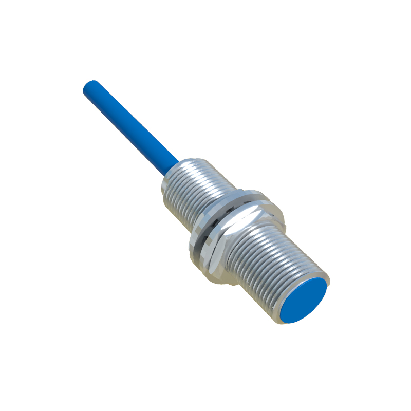
Prior to initiating any adjustment procedure, ensure all safety protocols are strictly followed. De-energize and lock out the associated machinery or control system to prevent accidental startup. Gather the necessary tools, which typically include the sensor's manual, a set of precision screwdrivers or potentiometer adjustment tools, a reliable measuring device (calipers or a distance gauge), and the appropriate monitoring equipment. For analog sensors, a multimeter or an oscilloscope is essential for reading the output voltage or current. For sensors with digital interfaces or programmable controllers, ensure you have the correct configuration software and communication cables. A stable test environment, free from excessive vibration, temperature fluctuation, or electromagnetic interference from other equipment, is crucial for obtaining accurate readings.
Identifying Adjustment Points and Parameters
Most industrial proximity sensors feature built-in adjustment mechanisms. The most common is a potentiometer, a small variable resistor accessible via a screw slot. This potentiometer controls the sensor's sensitivity or threshold level. Other sensors may have DIP switches for setting operating modes (e.g., light-on/dark-on for photoelectrics) or teach-in buttons for programming detection points. Network-enabled sensors might require parameter adjustment through software. The key parameters you will be adjusting are the sensing distance threshold and the hysteresis. The threshold determines the exact point at which the sensor switches its output state. Hysteresis is a built-in dead band that prevents output oscillation when the target is at the very edge of the detection point, ensuring a stable signal.
Step-by-Step Calibration Procedure
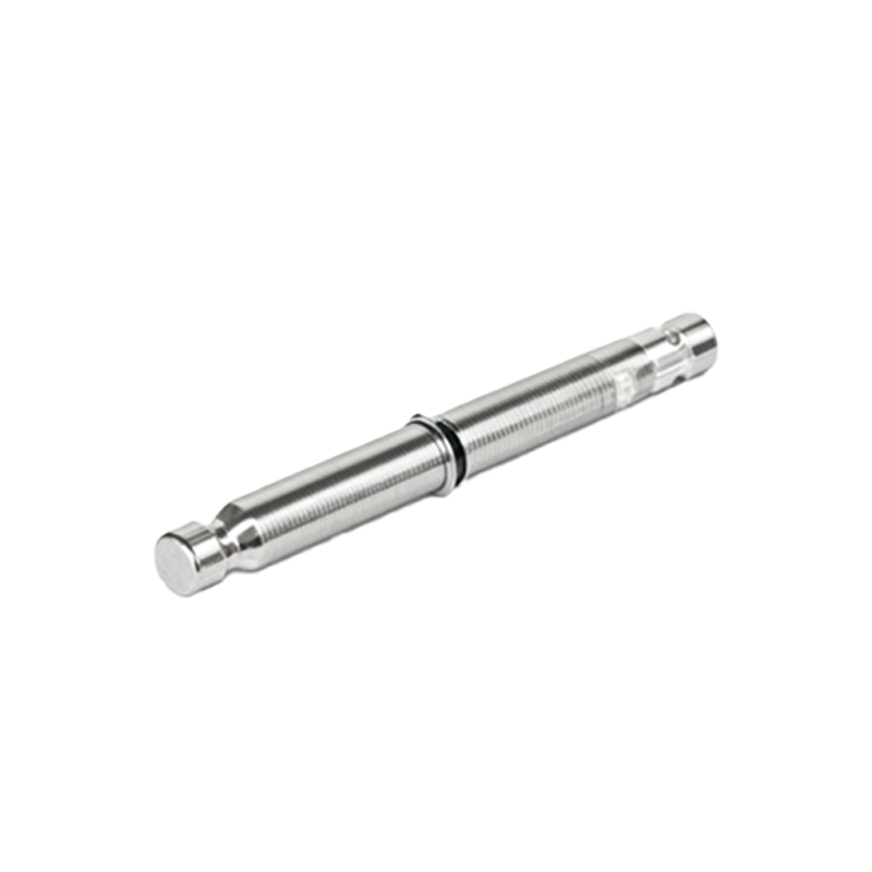
Begin by mounting the sensor and the target object in their intended operational positions. For distance calibration, use your measuring device to position the target at the desired detection point. Power the sensor and connect your monitoring tool (multimeter/oscilloscope) to its output wires. Observe the initial output value. Slowly adjust the sensitivity potentiometer while monitoring the output. For a digital sensor, you will observe a clear switch from "OFF" to "ON" (e.g., 0V to 24V). For an analog sensor, you will see a smooth change in voltage or current proportional to distance. Adjust until the output changes state precisely when the target reaches the intended position. Move the target in and out of the sensing field several times to test repeatability. Fine-tune the adjustment to account for any mechanical play or environmental factors, ensuring consistent and reliable triggering.
Verifying and Optimizing Sensor Performance
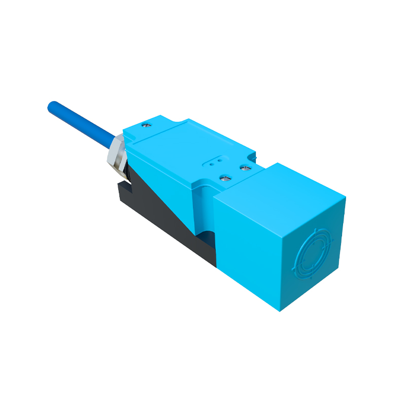
After the initial calibration, comprehensive verification is necessary. Test the sensor with the target at various points within its range, especially at the minimum and maximum intended distances. Check for false triggers by introducing non-target materials that might be present in the operating environment (e.g., metal chips near an inductive sensor, or ambient light for a photoelectric sensor). Evaluate the response time to ensure it meets the application's speed requirements. If the sensor exhibits instability (chattering), you may need to slightly increase the hysteresis setting if available, or re-check for sources of electrical noise or vibration. Document the final adjustment settings, such as the potentiometer position or software parameters, for future reference and maintenance.
Troubleshooting Common Adjustment Issues
If the sensor fails to adjust properly, systematic troubleshooting is required. First, verify the power supply voltage is within the sensor's specified range. Check all wiring connections for looseness or corrosion. Ensure the target object's material, size, and shape are suitable for the sensor type; for instance, a capacitive sensor may detect a non-metallic object that an inductive sensor will ignore. If the output is erratic, investigate potential sources of interference, such as adjacent motors, welding equipment, or other sensors operating on similar frequencies. Shielding cables or increasing the physical separation from noise sources can often resolve this. If the sensor cannot achieve the required sensing distance, it may be under-specified for the application