Introduction to Proximity Sensor Fundamentals
Proximity sensors are indispensable components in modern industrial automation, providing non-contact detection of objects within a defined sensing range. Unlike mechanical limit switches, they operate without physical contact, offering superior reliability, longevity, and speed. The core function of any proximity sensor is to detect the presence or absence of a target object and convert this information into an electrical signal. This detection is achieved through various physical principles, primarily inductive, capacitive, and photoelectric methods. Each type employs a distinct internal schematic and operational theory tailored to specific material properties and environmental conditions. Understanding these internal schematics is crucial for engineers to select the appropriate sensor, troubleshoot issues, and integrate them effectively into complex control systems. The internal architecture, while varying by type, generally consists of an oscillator circuit, a signal conditioning unit, a detection circuit, and an output stage, all housed within a robust casing.
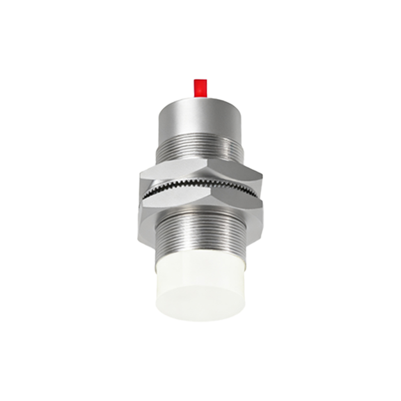
Anatomy of an Inductive Proximity Sensor Schematic
Inductive proximity sensors are designed to detect metallic objects, primarily ferrous metals like iron and steel. The internal schematic revolves around a high-frequency oscillator circuit. This circuit generates an oscillating electromagnetic field at the sensing face, which is emitted by a coil wound around a ferrite core. When a metallic target enters this alternating magnetic field, eddy currents are induced on the surface of the target. These eddy currents draw energy from the oscillator, causing a measurable reduction in the oscillation amplitude. A subsequent detection circuit, often a Schmitt trigger or a comparator, continuously monitors this amplitude. Once the amplitude drop exceeds a predefined threshold, the detection circuit triggers a change in the output state. The output stage then switches, typically using a solid-state NPN or PNP transistor, to provide a clean digital signal (e.g., 24V DC or 0V) to the programmable logic controller (PLC). Key components in this schematic include the LC tank circuit (coil and capacitor) for oscillation, a dedicated IC for signal processing, and protection circuits against reverse polarity, short-circuits, and voltage spikes.
Deciphering the Capacitive Proximity Sensor Design
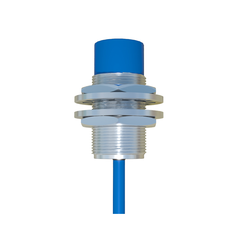
Capacitive proximity sensors can detect both metallic and non-metallic materials, including liquids, plastics, and wood. Their internal schematic is conceptually similar to that of an inductive sensor but operates on the principle of capacitance change. The sensor face acts as one plate of a capacitor, with the target object acting as the other plate, and the air gap as the dielectric. The internal circuit includes an oscillator whose frequency is determined by this formed capacitance. When a target object approaches the active face, the capacitance of the system increases. This change in capacitance alters the oscillator's frequency or amplitude. A dedicated evaluation circuit detects this shift. Unlike inductive sensors, capacitive models often feature a sensitivity adjustment potentiometer. This allows engineers to calibrate the sensor to ignore certain materials or backgrounds, preventing false triggers. The output stage is similar, providing a switched signal. The schematic must carefully manage stray capacitance and often includes shielding to ensure the sensor only reacts to the front-facing detection field, making its internal layout and grounding critically important for stable operation.
Photoelectric Sensor Internal Architecture
Photoelectric sensors operate on the principle of light transmission, reflection, or interruption. Their internal schematic is distinctly different from inductive and capacitive types. The core components are an emitter (light source—typically an LED, often infrared) and a receiver (phototransistor or photodiode). In a thru-beam sensor, these are separate units; in a retro-reflective or diffuse sensor, they are housed together. The emitter is driven by a constant current circuit to ensure stable light intensity. The receiver circuit is highly sensitive, designed to convert received light photons into a small electrical current. This minute current is fed into a high-gain amplifier. The amplified signal is then compared to a threshold level by a comparator circuit. Environmental factors like ambient light or dust can interfere, so advanced schematics incorporate modulation/demodulation techniques. The emitter light is pulsed at a specific high frequency, and the receiver circuit is tuned to only amplify signals at that same frequency, effectively filtering out background optical noise. This requires a more complex internal schematic with timing circuits and specialized ICs for synchronous detection.
Output Stage and Protection Circuitry
Regardless of the sensing technology, the output stage is a critical part of the internal schematic that interfaces with the external control system. Most industrial proximity sensors feature a solid-state transistor output (DC sensors) or a relay (some AC/DC models). The transistor, whether NPN (sinking) or PNP (sourcing), acts as a fast, wear-free switch. The schematic includes base-drive resistors and often a flyback diode for