Understanding Proximity Sensor Sensitivity
Proximity sensors are fundamental components in industrial automation, providing non-contact detection of objects. Their sensitivity, defined as the maximum distance at which the sensor can reliably detect a standard target, is a critical parameter. However, an overly sensitive sensor can become a significant source of operational headaches. Instead of detecting only the intended target, it may trigger falsely due to environmental factors, nearby machinery, or even vibrations. This leads to nuisance trips, production line stoppages, and reduced system reliability. The core issue often lies not in the sensor being "defective," but in a mismatch between its inherent capability and the specific application environment. Sensitivity is typically adjustable on most modern inductive, capacitive, and photoelectric sensors, making calibration a primary troubleshooting step.
Primary Calibration and Adjustment Methods
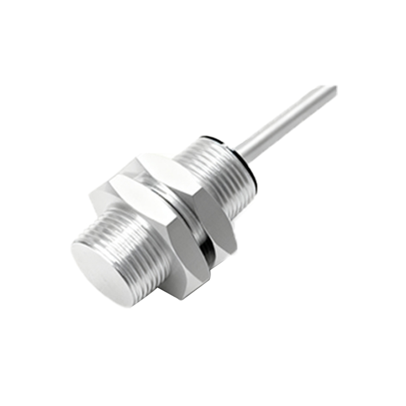
The first and most direct line of defense is proper calibration. Most proximity sensors feature a potentiometer or a teach-in function for sensitivity adjustment. Begin by identifying the sensor's data sheet to understand its adjustment range. Using the specified target material and size, position it at the desired nominal sensing distance. Gradually reduce the sensitivity setting until the sensor's output just barely activates with the target in place. Then, verify that the sensor does not activate when the target is removed. For applications with varying targets or environmental conditions, it is advisable to set the sensitivity with a 10-20% margin from the trigger point to ensure stability. For digital sensors with push-button programming, follow the manufacturer's sequence to set the sensing window accurately, effectively ignoring objects outside this range.
Mitigating Environmental Electrical Noise
Electrical noise is a prevalent cause of false triggering that can mimic excessive sensitivity. Noise can be induced from AC power lines, variable frequency drives (VFDs), welding equipment, or high-current switching. To combat this, ensure all sensor wiring, especially output and signal lines, is routed separately from power cables. Using shielded cables and properly grounding the shield at the controller end (not both ends) is essential. For DC sensors, incorporating a flyback diode or a surge suppressor across the load can clamp voltage spikes. In severe noise environments, consider switching to a sensor with a differential output or one that operates on a different frequency, if available. Always verify that the power supply is clean and stable, as voltage fluctuations can also affect performance.
Addressing Physical and Mechanical Interference
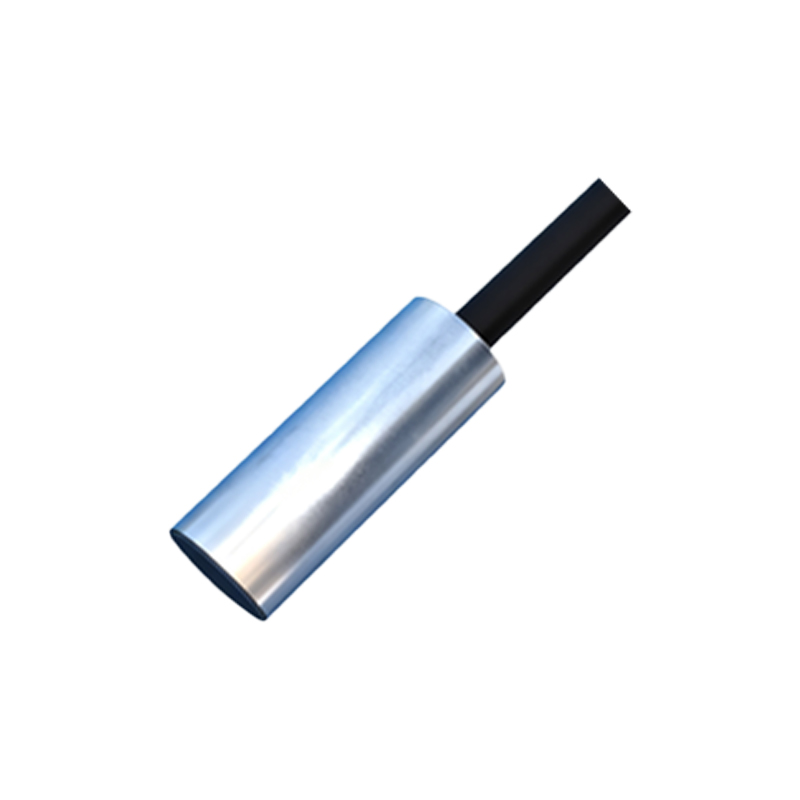
Sometimes, the problem is physical. Vibrations can cause a sensor to move minutely, changing the gap to a metal background or bracket, which then triggers a false detection. Ensure the sensor is securely mounted using appropriate brackets to minimize resonance. For inductive sensors detecting metallic objects, be mindful of the sensor's lateral sensing area. A large metal structure passing nearby, like a machine guard or a conveyor frame, might be within this lateral range. Increasing the physical gap between the sensor and such structures or using a sensor with a shielded (flush-mountable) design can eliminate this issue. For photoelectric sensors, airborne dust, oil mist, or condensation on the lens can scatter light and cause false triggers, necessitating regular cleaning or the use of sensors with built-in contamination indicators.
Selecting the Correct Sensor Type and Technology
If adjustment and environmental fixes prove insufficient, the root cause may be an incorrect sensor choice. An inductive sensor might be too sensitive for an application with many stray metal chips. Switching to a capacitive sensor with better material discrimination or a sensor with a reduced sensing range could be the solution. For detecting small objects, a focused-beam photoelectric sensor might perform better than a diffuse model that is sensitive to a broad background. Ultrasonic sensors offer excellent material independence but can be sensitive to air turbulence; laser sensors provide precise, small spot detection. Review the application requirements: target material, size, required sensing distance, and environmental conditions. Often, selecting a sensor whose default sensitivity range is more closely matched to the operational need is more effective than trying to de-tune a highly sensitive unit.
Implementing Delay Timers and Logic Control
When sensor sensitivity cannot be further reduced without risking missed detections, or in inherently noisy applications, adding external logic can provide a robust solution. Programmable Logic Controllers (PLCs) or simple timer relays can be used to implement delay functions. An "ON-delay" timer requires the sensor signal to be present continuously for a set duration (e.g., 50-200 milliseconds) before registering a true detection, filtering out brief, spurious signals. Conversely, an "OFF-delay" can hold the output on briefly after the target leaves, preventing chatter during edge transitions. For complex scenarios, a voting logic (e.g., 2 out of 3 sensors