Understanding Proximity Sensor Non-Response
A proximity sensor failing to register an object is a common yet critical issue in industrial automation. This non-response halts production lines, causes machine faults, and leads to significant downtime. Fundamentally, a proximity sensor detects the presence or absence of a metallic or non-metallic target without physical contact, typically through inductive, capacitive, or ultrasonic principles. When it "reads nothing," it means the sensor's output state does not change as expected when a valid target enters its sensing range. The root cause is rarely the sensor itself being completely dead; more often, it's a mismatch between the sensor's operational parameters and the application's real-world conditions. Initial troubleshooting must always begin with verifying the basics: power supply integrity, correct wiring as per the datasheet, and ensuring the target is indeed within the specified nominal sensing distance.
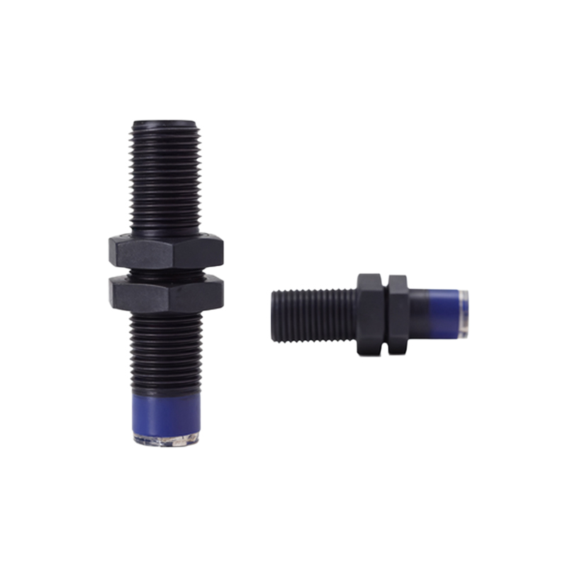
Primary Causes of Detection Failures
Several technical factors can lead to a sensor not detecting a target. First, Incorrect Sensor Type Selection is paramount. Using an inductive sensor to detect a plastic object, or a capacitive sensor in a environment with fluctuating humidity, will result in failure. Second, Installation and Mechanical Issues are frequent culprits. Misalignment between the sensor and the target, excessive side-to-side gap, or a build-up of dirt, metal shavings, or oil on the sensing face can drastically reduce the effective sensing distance. Third, Electrical and Environmental Interference can disrupt operation. Voltage spikes, electromagnetic interference from nearby motors or drives, or welding currents can swamp the sensor's sensitive electronics. Similarly, extreme temperatures beyond the sensor's rated specification can cause internal component drift or failure.
Step-by-Step Diagnostic Procedure
A systematic approach is essential for efficient diagnosis. Start with a Visual and Physical Inspection. Check for obvious physical damage, contamination on the sensing face, and ensure the target is present and correctly positioned. Listen for the faint click of a mechanical relay output if applicable. Next, perform Electrical Measurements. Use a multimeter to confirm the power supply voltage at the sensor's terminals is stable and within the specified range (e.g., 10-30V DC). Measure the output voltage or current in both states (target present and absent). A sinking (NPN) sensor should pull the output close to 0V when active, while a sourcing (PNP) sensor should pull it close to the supply voltage. A lack of change indicates a problem.
Advanced Troubleshooting Techniques
If basic checks pass, deeper investigation is needed. Oscilloscope Analysis of the output signal can reveal issues like noise, slow switching times, or a degraded signal that a PLC input might not reliably register. Sensor Adjustment and Testing is crucial. Many sensors have a potentiometer or teach-in function to adjust sensitivity. Temporarily increasing the sensitivity can help determine if the issue is a marginal signal. Test the sensor with a standard metal target (like a coin or wrench) at close range in a controlled setting to isolate it from the machine environment. This confirms if the sensor itself is functional. Additionally, check for Load Compatibility. Ensure the sensor's output current rating is sufficient for the connected load (e.g., PLC input, relay coil). An overloaded output may appear to fail.
Implementing Robust Solutions and Preventative Measures
Resolving the immediate failure is only half the battle. Implementing long-term solutions prevents recurrence. Select Sensors with Adequate Margin: Always choose a sensor with a rated sensing distance (Sn) 20-30% greater than the application requires to account for mechanical tolerances, temperature effects, and contamination. Employ Proper Shielding and Filtering: Use shielded cables, grounded properly at one end, to mitigate EMI. Install surge protectors or RC networks on inductive loads. For noisy environments, select sensors with built-in noise immunity or short-circuit protection. Establish Regular Maintenance Schedules: Include sensor cleaning, mechanical alignment checks, and functional testing in preventative maintenance routines. Log environmental conditions to identify correlated failure patterns.
Conclusion: Ensuring Reliable Sensing Performance
A proximity sensor reading failure is a solvable engineering challenge. The key lies in moving beyond simple part replacement to a diagnostic mindset that considers the entire system: the sensor's specifications, the target's properties, the electrical environment, and the mechanical installation. By adhering to a structured troubleshooting flow—from visual inspection to electrical verification and environmental analysis—engineers can quickly restore operation. Ultimately, investing time in correct sensor selection, robust installation practices, and proactive maintenance is the most effective strategy for maximizing uptime and ensuring the reliable, unseen operation of these critical industrial components.