Introduction to 2-Wire Proximity Sensors
Two-wire proximity sensors are widely used in industrial automation due to their simplicity and cost-effectiveness. Unlike three-wire or four-wire sensors, they integrate the power supply and signal output into a single pair of wires, reducing wiring complexity and installation time. These sensors are commonly employed in applications such as object detection, position sensing, and limit switching in machinery. Understanding their wiring is crucial for ensuring reliable operation and avoiding common pitfalls like incorrect load connection or voltage drop issues. This article provides a detailed wiring diagram and step-by-step guidance for proper installation.
Working Principle and Key Components
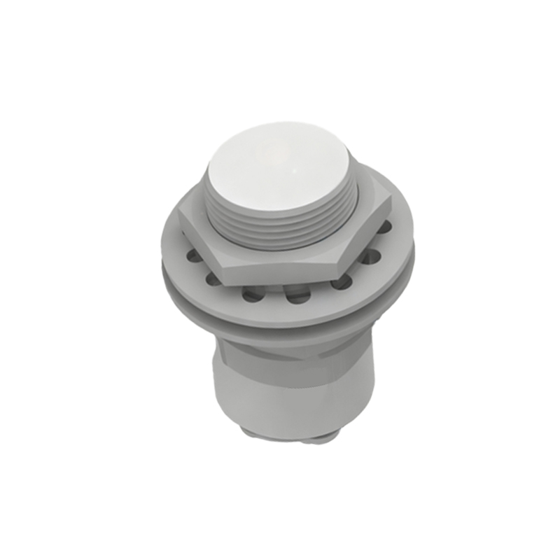
A 2-wire proximity sensor operates by generating an electromagnetic field to detect metallic or non-metallic objects within its sensing range. When an object enters this field, it causes a change in the sensor's internal oscillation, triggering the output switch. The two wires serve dual functions: one connects to the positive DC voltage supply (typically 10-30V DC), while the other links to the load (e.g., a PLC input, relay, or indicator). The sensor's output is normally open (NO) or normally closed (NC), with the switching element—often a solid-state device—embedded within the unit. Key components include the sensing face, oscillator, demodulator, and output circuit, all designed to handle the combined power and signal transmission through the same wires.
Detailed Wiring Diagram and Connections
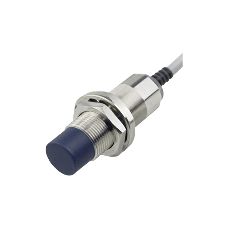
The wiring diagram for a 2-wire proximity sensor involves connecting it in series with the power supply and load. First, identify the sensor's polarity: most models are DC-powered and require correct positive (+) and negative (-) connections. Connect the positive wire from the DC power source (e.g., 24V DC) to the sensor's brown wire (or as per manufacturer labeling). Then, link the sensor's blue wire (or designated output wire) to one terminal of the load. Finally, connect the other load terminal to the negative side of the power supply. Ensure all connections are secure to prevent voltage drops. A typical diagram shows: Power Supply (+) → Sensor Brown Wire → Sensor Blue Wire → Load → Power Supply (-). Always refer to the sensor's datasheet for specific color codes and ratings.
Common Installation Mistakes and Solutions
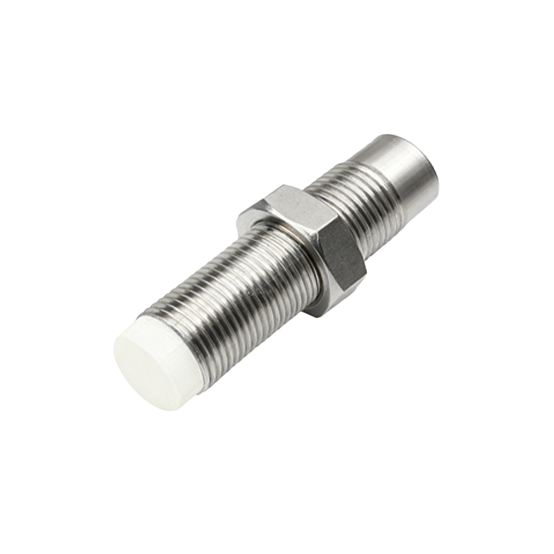
Incorrect wiring is a frequent issue when installing 2-wire proximity sensors. One common mistake is reversing the polarity, which can damage the sensor or cause malfunction. To avoid this, double-check the wire colors and markings before powering up. Another error involves overloading the sensor by connecting a load that exceeds its current rating (usually 200mA-500mA). Use a load within the specified range, and consider adding an external relay for high-current devices. Voltage drop across the sensor can also lead to unreliable operation, especially with long wire runs or high-impedance loads. Minimize this by using shorter cables and ensuring adequate power supply voltage. Regularly test the sensor with a multimeter to verify output stability.
Advantages and Limitations in Industrial Use
The primary advantage of 2-wire proximity sensors is their streamlined wiring, which cuts installation costs and reduces cabinet space. They are also compatible with standard PLC inputs and require no separate power wiring, making them ideal for retrofitting existing systems. However, limitations include a voltage drop (typically 2-4V) across the sensor, which can affect low-voltage circuits. Additionally, they may have lower switching frequencies compared to three-wire versions, and leakage current (a small current flow even when off) can sometimes trigger sensitive loads. To mitigate these, select sensors with low voltage drop and leakage current specifications, and use shielded cables in electrically noisy environments.
Maintenance and Troubleshooting Tips
Regular maintenance ensures longevity and accuracy of 2-wire proximity sensors. Start by visually inspecting the sensor for physical damage or contamination on the sensing face. Clean it with a soft cloth to remove dust or oil buildup. Check wiring connections for corrosion or looseness, and measure the supply voltage and output signal with a multimeter. If the sensor fails to detect objects, verify the sensing distance and alignment—objects outside the rated range may not trigger a response. For intermittent operation, test for electrical interference by relocating cables away from motors or high-voltage lines. Replace the sensor if it shows consistent errors or no output, and always follow lockout-tagout procedures during troubleshooting.
Conclusion and Best Practices
Proper wiring of 2-wire proximity sensors is essential for efficient industrial automation. By following the diagram and guidelines outlined above, engineers can ensure reliable detection and system integration. Key best practices include