In industrial automation, proximity sensors play a critical role in detecting the presence or absence of objects without physical contact. While much attention is given to their sensing range and environmental ratings, a frequently overlooked aspect is the electrical load they are designed to drive. Properly understanding and managing this load is fundamental to ensuring reliable operation, long sensor life, and system stability.
At its core, the "load" refers to the electrical device the proximity sensor's output signal controls. This is typically the input of a Programmable Logic Controller (PLC), a relay coil, or the coil of a contactor. Sensors are not power sources; they are switching devices. Their solid-state outputs (like NPN or PNP transistors) or electromechanical relay outputs are designed to handle a specific maximum current and voltage. Exceeding these ratings can lead to immediate failure or gradual degradation.
There are two primary output types with distinct load characteristics. Solid-state outputs (DC sensors) are fast, have no moving parts, and are long-lasting, but they have strict current and voltage limits (e.g., 200mA max, 30V DC). They are sensitive to overloads, short circuits, and incorrect polarity. Inductive loads like relay coils can generate voltage spikes when de-energized, which can damage the sensor's internal transistor. Conversely, relay outputs provide physical isolation and can often switch higher currents for both AC and DC loads. However, they have a slower switching speed, mechanical wear, and can cause electrical noise (arcing) during operation.
A key concept in load management is inrush current. Many loads, especially solenoid coils and contactors, require a significantly higher current to activate (inrush) than to hold. A sensor rated for 500mA continuous current might see a 2A inrush spike for 20 milliseconds. If the sensor cannot handle this transient peak, its output may weld shut or fail. Always consult the sensor's datasheet for both continuous and peak (inrush) current ratings.
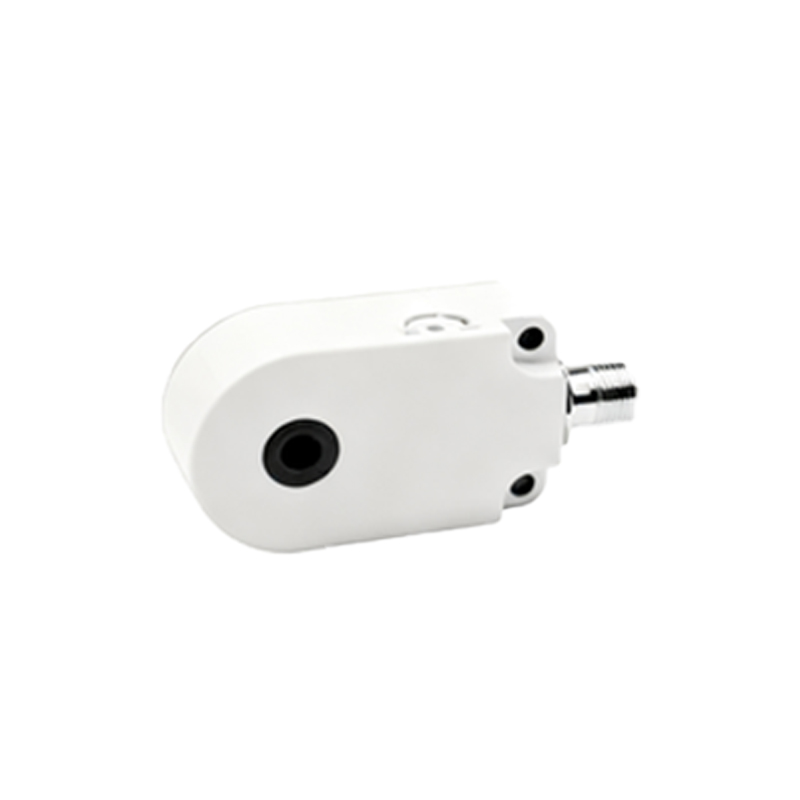
For DC solid-state sensors driving inductive loads, protection is mandatory. A flyback diode (or freewheeling diode) must be installed in parallel with the inductive load. This diode provides a safe path for the collapsing magnetic field's current when the sensor switches off, preventing a damaging reverse voltage spike from reaching the sensor. For AC loads, a snubber circuit (RC network) or a metal-oxide varistor (MOV) is often used across the load to suppress voltage transients.
Mismatched loads are a common source of failure. Using a 10V sensor to switch a 24V load will not work. Using a sensor with a 100mA rating to directly power a lamp drawing 500mA will overload it. Always verify that the load's operational voltage matches the sensor's output rating and that the load's steady-state and inrush currents are within the sensor's specified limits. When in doubt, use an intermediate relay: let the sensor switch a small, compatible relay coil, and let that relay's contacts handle the larger, problematic load.
Resistive loads (like indicator lamps) are generally the simplest to drive. Inductive loads (relays, solenoids, motors) require protection against voltage spikes. Capacitive loads, though less common, can cause high inrush currents and require current-limiting resistors. Always consider the worst-case scenario in the system's operating environment.
In summary, treating a proximity sensor's load specification as a critical selection parameter prevents countless field issues. System designers must move beyond just the sensing distance and look closely at the electrical characteristics of the device being controlled. By matching ratings, implementing protective components for reactive loads, and using intermediary devices when necessary, the full reliability and longevity of proximity sensing systems can be achieved. This proactive approach to load consideration minimizes downtime and ensures robust performance in demanding automation environments.