Laser displacement sensors are critical components in modern industrial automation, providing high-precision, non-contact measurement for tasks like thickness gauging, vibration analysis, and part positioning. A correct electrical connection is fundamental to their reliable operation. This guide provides a comprehensive overview of standard wiring configurations, using typical connection diagrams as a reference.
Most industrial laser displacement sensors operate on a DC power supply, commonly 12-24 VDC. The connection terminals are usually located in a connector or a terminal block housing on the sensor body. A standard wiring setup involves three main groups of cables: power supply, output signal, and communication (if available).
1. Power Supply Wiring
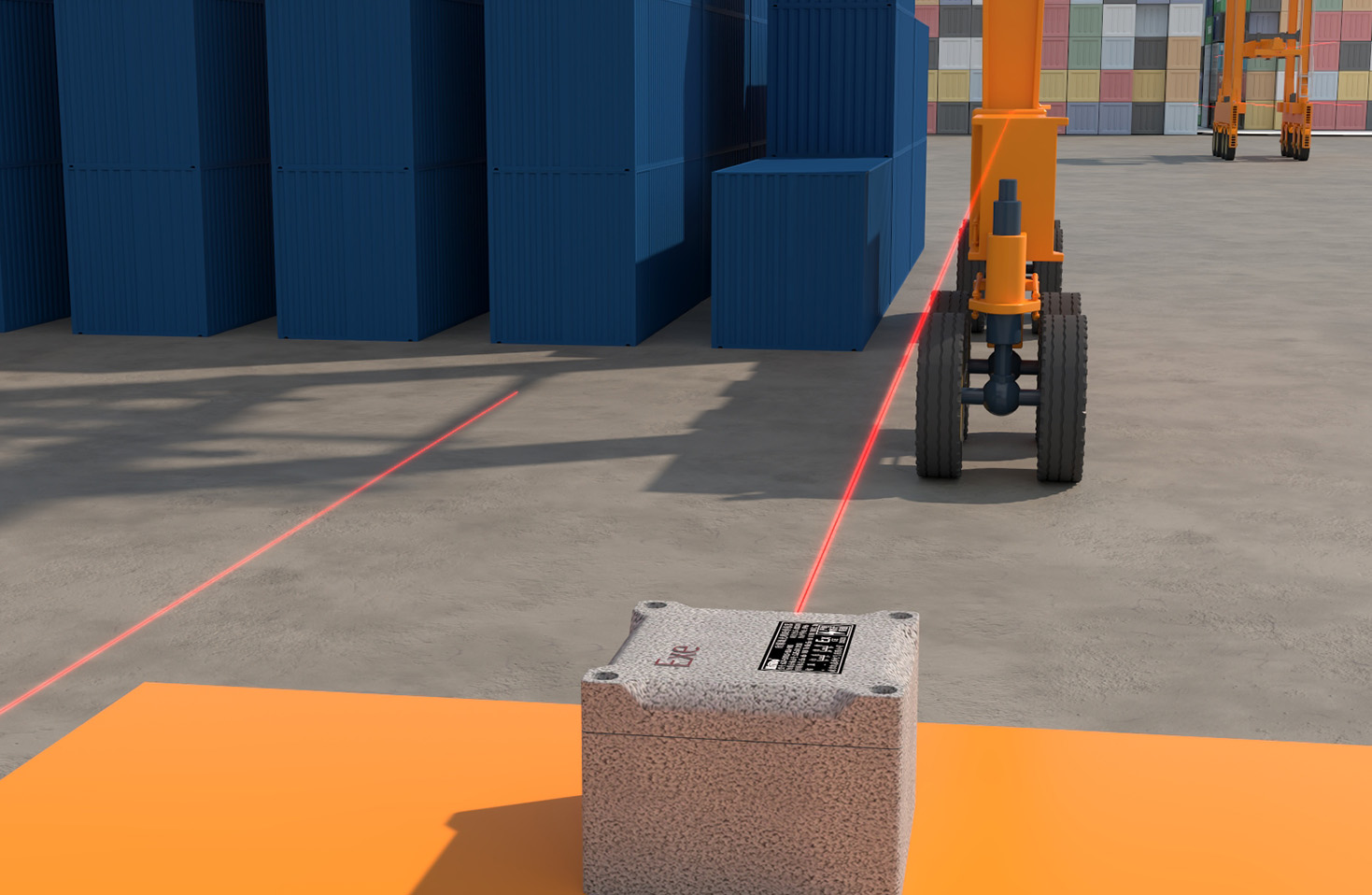
The foundation of any connection is the power circuit. Identify theV+ (or+Vs) and0V (orGND,COM) terminals on your sensor's datasheet diagram. Connect the positive lead from your regulated DC power source to theV+ terminal. Connect the negative lead from the power source to the0V terminal. It is crucial to ensure the voltage matches the sensor's specification (e.g., 24 VDC ±10%). An unstable or incorrect power supply is a primary cause of sensor malfunction or damage. Always use a fused power line for protection.
2. Output Signal Wiring
Laser sensors convert distance measurements into electrical signals. Common output types include Analog (voltage or current), Digital (NPN/PNP transistor, or push-pull), and Switch (discrete limits). The wiring differs for each.
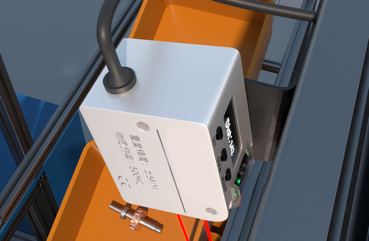
* Analog Output (e.g., 0-10V, 4-20mA): For a voltage output, you will typically findVout andGND (often shared with power GND) terminals. ConnectVout to the analog input channel of your controller (PLC, data acquisition card). For a 4-20mA current output, connect theIout terminal to the positive input of your current-reading device; the loop is completed back to the power common. Always refer to the diagram for specific terminal labels likeAO1 orIOUT.
* Digital NPN/PNP Output: These are open-collector transistor outputs for switching. An NPN sensor (sinking) switches theOUT terminal to0V. To wire it, connect the load (e.g., a PLC digital input) between theOUT wire and the positive supply (V+). A PNP sensor (sourcing) switches theOUT terminal toV+. Here, connect the load between theOUT wire and0V. The datasheet diagram will clearly indicate whether the output is NPN or PNP.
* Dual Discrete Outputs: Some sensors have two independent switch outputs (e.g.,OUT1,OUT2) for high/low limit alarms. Each is wired as a separate NPN or PNP circuit to different controller inputs.
3. Communication & Auxiliary Wiring
Advanced sensors feature serial communication (RS-422, RS-485) or industrial Ethernet (EtherCAT, PROFINET) for configuration and data streaming. For RS-485, you will connect wires toDATA+,DATA, and a signal ground, often in a daisy-chain topology. Ethernet models typically use a standard RJ45 connector. Always use shielded cables for communication lines and ground the shield at one end to prevent electrical noise interference.
Some sensors also have auxiliary inputs for functions like external triggering (TRIG) or output enable (ENABLE). These are typically connected to a PLC's digital output or a simple switch.
Safety and Best Practices
* Always Power Down: Disconnect power before making or changing any connections.
* Follow the Specific Diagram: The above is a general guide. The exact terminal names, pin assignments, and cable colors vary by manufacturer (e.g., Keyence, Panasonic, Banner, Micro-Epsilon). The only authoritative source is the connection diagram in the official product manual for your specific model number.
* Use Proper Cabling: Employ shielded, twisted-pair cables for analog and communication signals. Keep these cables separate from high-voltage AC power lines to minimize noise.
* Secure Connections: Ensure all terminal screws are tightened or connectors are fully seated to prevent intermittent faults.
* Verify with a Multimeter: Before powering the system, check for short circuits between terminals. After powering, verify the supply voltage at the sensor connector.
A correctly wired sensor, based on a precise understanding of its connection diagram, ensures stable power delivery, clean signal transmission, and immunity to electrical noise. This directly translates to measurement stability, system reliability, and reduced downtime in automated production and quality control environments. If discrepancies arise between sensor readings and expected values, the wiring connections and grounding are the first elements to inspect and verify against the provided schematic.