Understanding Proximity Sensor Mini Fundamentals
Proximity sensors mini, often referred to as miniature proximity sensors, are compact devices designed to detect the presence or absence of an object within a short range without physical contact. Operating on principles like inductive, capacitive, or photoelectric sensing, these sensors generate an electromagnetic field or beam. When a target object disrupts this field, the sensor's state changes, triggering an output signal. Their miniaturized form factor makes them ideal for applications with severe space constraints, such as in robotics, automated assembly lines, and compact machinery. Key specifications to consider include sensing distance, which is typically a few millimeters for mini models, response frequency, output type (PNP/NPN, NO/NC), and the material of the detectable target. Understanding these core operational principles is the first critical step toward their effective implementation.
Selecting the Right Miniature Proximity Sensor
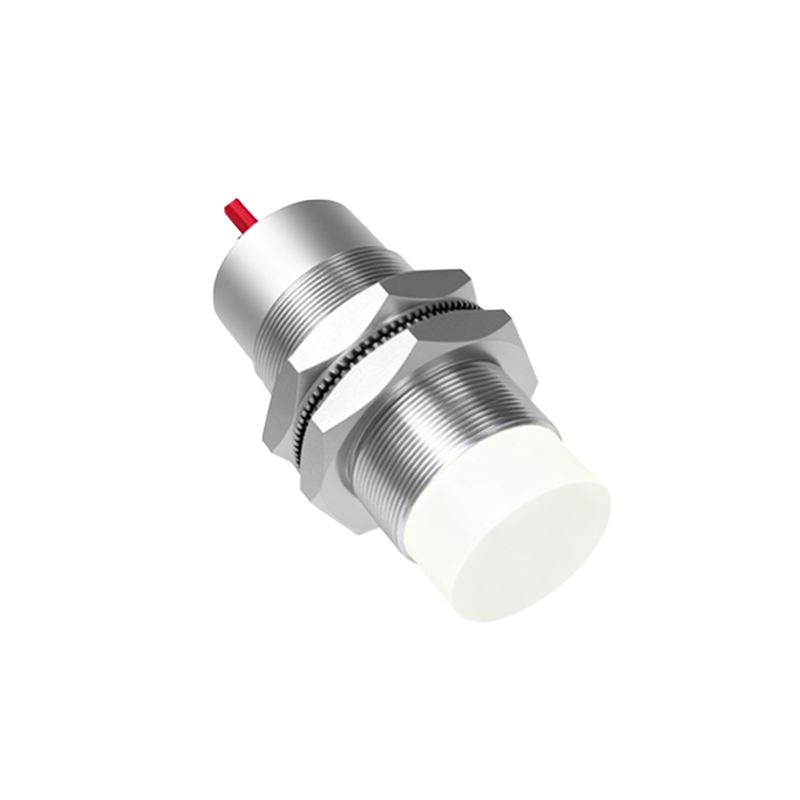
Choosing the correct sensor is paramount for system reliability. For metallic objects, especially ferrous metals like iron and steel, inductive proximity sensors are the standard choice due to their robustness and precision. For non-metallic materials such as plastic, wood, or liquids, a capacitive mini sensor is required. If the application involves detecting small objects or requires precise positioning, a miniature photoelectric sensor, either through-beam or diffuse reflective, might be the optimal solution. Engineers must meticulously evaluate the operating environment—factors like temperature extremes, potential exposure to oils or coolants, and electrical noise. Selecting a sensor with an appropriate IP (Ingress Protection) rating ensures durability in harsh industrial settings.
Proper Installation and Mounting Techniques
Incorrect installation is a common source of sensor failure. For inductive and capacitive sensors, maintaining the correct mounting distance is crucial. There must be adequate clearance around the sensing face, known as the "mounting flush" area, as specified by the manufacturer. Embedding the sensor in metal can reduce its effective sensing range. Always secure the sensor firmly to prevent vibration-induced misalignment. Pay close attention to cable routing; cables should be kept away from high-voltage power lines and motor drives to minimize electromagnetic interference. Utilizing shielded cables and proper grounding techniques significantly enhances signal integrity and system stability in electrically noisy environments.
Wiring and Electrical Connection Procedures
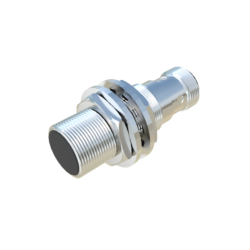
Accurate wiring is essential for safe and functional operation. Most miniature proximity sensors operate on DC voltages, commonly 12-24V DC. The output configuration must match the input requirements of the connected controller (PLC, relay, etc.). A 3-wire sensor with a PNP (sourcing) output provides a positive voltage signal when activated, while an NPN (sinking) output connects the load to ground. Carefully consult the sensor's datasheet for the wiring diagram. Connect the brown wire (typically +V), the blue wire (typically 0V or common), and the black wire (output signal). Always ensure power is disconnected during wiring. Incorporating a protective fuse in the circuit and, if necessary, a surge suppressor for inductive loads, safeguards the sensor from electrical damage.
Configuration, Testing, and Calibration
After installation and wiring, the system requires configuration and testing. Power on the circuit and use a simple test object, such as a metal plate for inductive sensors, to verify detection. Observe the indicator LED on the sensor (if available) and monitor the input status on the PLC or controller. For adjustable sensors, fine-tune the sensitivity potentiometer to achieve reliable detection while avoiding false triggers from background objects or environmental noise. In critical applications, establish a routine calibration schedule. Document the sensing distance achieved under normal conditions to facilitate quick diagnostics during future maintenance. Testing under the full range of expected operating conditions is necessary to confirm robustness.
Troubleshooting Common Operational Issues
Even with proper installation, issues may arise. If a sensor fails to detect an object, first check the power supply voltage with a multimeter. Verify the wiring connections against the diagram. Inspect the sensing face for accumulation of dirt, metal chips, or other contaminants that can attenuate the sensing field. For inconsistent operation, investigate potential interference from adjacent sensors, motors, or welding equipment. Increasing the physical separation between sensors or switching to sensors with different operating frequencies can resolve crosstalk. If the sensor activates without a target present, reduce the sensitivity setting or check for moving background objects like conveyor frames within the extended sensing range.
Implementing Advanced Applications and Integration
The versatility of proximity sensors mini enables sophisticated applications. They are integral to providing positional feedback in linear actuators, counting products on high-speed packaging lines, and ensuring safety in automated systems by verifying the position of guards or doors. In modern Industry 4.0 setups, these sensors