Introduction to Proximity Sensing and Lever Actuation
Proximity sensors are fundamental components in industrial automation, providing non-contact detection of objects. However, direct sensing is not always feasible due to space constraints, environmental factors, or the need to detect objects in hard-to-reach locations. This is where lever mechanisms become indispensable. A lever actuator, when integrated with a proximity sensor, extends its functional range and adapts its sensing capability to specific mechanical configurations. Essentially, the lever translates a physical movement or presence at one point into a precise actuation at the sensor's sensing face. This article delves into the mechanics, types, applications, and critical design considerations of lever mechanisms used with proximity sensors, providing clear diagrams for better understanding.
Core Components and Working Principle
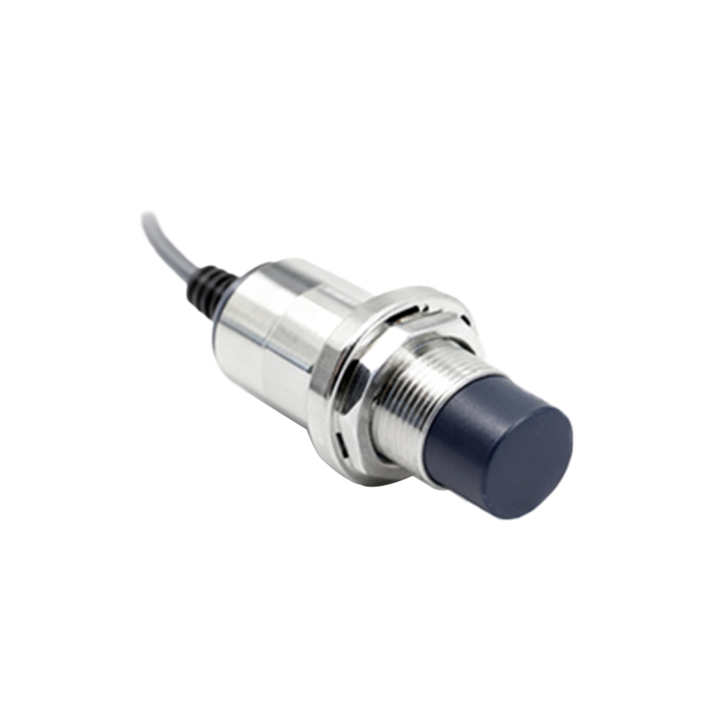
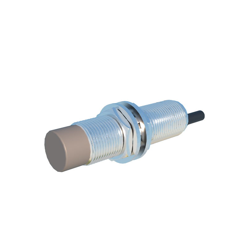
The system comprises two main parts: the proximity sensor (typically inductive or capacitive) and the lever actuator assembly. The sensor itself contains an oscillator circuit and a sensing coil. The lever assembly consists of a pivot point (fulcrum), an actuator arm, and a sensing tip or roller. When an object contacts the actuator arm's tip, it causes the lever to rotate around its pivot. This rotational motion is transferred to a small metallic or dielectric target attached to the opposite end of the lever, positioned directly in front of the sensor's sensing face. As this target moves into the sensor's active electromagnetic field, it causes a change in the oscillation amplitude or frequency. The sensor's internal circuitry detects this change and triggers a solid-state output switch, signaling the object's presence. The mechanical advantage of the lever allows for the detection of very small movements or forces at the contact point.
Common Types of Lever Actuator Designs
Several lever designs cater to different application needs. The Pivot Lever is the most common, featuring a straight arm rotating around a central pivot. It offers simple, reliable operation for lateral object detection. The Roller Lever incorporates a small bearing or roller at the contact end. This design minimizes friction and wear when detecting moving objects, such as on conveyor lines, and prevents catching or snagging. The Forked Lever or Tuning Fork design has two prongs; an object passing through the fork deflects the actuator. This is ideal for detecting small parts or verifying the presence of an item in a specific path. Adjustable Lever arms allow for customization of the arm length or pivot position, enabling fine-tuning of the actuation point and force required. Diagrams typically show the lever's range of motion and the "dead zone" where movement does not actuate the sensor.
Key Application Areas in Industrial Settings
Lever-actuated proximity sensors are ubiquitous in manufacturing and packaging. In material handling, they are used as limit switches on automated guided vehicles (AGVs) or to detect the position of pallets on rollers. Machine tooling applications include tool breakage detection, where a broken drill bit fails to deflect a lever, triggering an alarm. They serve as safety interlocks on guards and doors, ensuring machinery only operates when panels are securely closed. Within assembly automation, they verify the presence and correct orientation of components before a process step. The roller lever type is particularly valuable in packaging lines for detecting the edge of film, carton presence, or product counting on high-speed conveyors, where direct sensor mounting is impractical.
Critical Selection and Design Considerations
Choosing the correct lever mechanism is vital for reliability. Operating Force and Overtravel are paramount: the mechanism must require minimal force to actuate to avoid impeding machine movement, and it must withstand overtravel (movement beyond the actuation point) without damage. Repeatability refers to the consistency of the actuation point; high-precision applications demand levers with minimal hysteresis. Environmental factors like temperature, exposure to coolants, oils, or washdowns dictate material choices, often stainless steel or engineered plastics. The Mechanical Life rating, often in millions of cycles, must exceed the application's expected lifecycle. Engineers must also consider the initial position (normally open or normally closed) and the pre-travel distance—the movement needed from free position to the switch point. Proper mounting to avoid side-loading on the pivot is essential for longevity.
Installation, Calibration, and Maintenance Tips
Proper installation begins with securely mounting the sensor body. The lever arm must be positioned so that the target object contacts it within its designed range of motion, avoiding extreme angles that cause binding. Ensure there is adequate clearance for the lever's full sweep. Calibration involves setting the sensor's sensing distance (usually fixed) and adjusting the mechanical