Understanding Proximity Sensor Fundamentals
Proximity sensors are non-contact electronic devices designed to detect the presence or absence of an object within their sensing field. Widely used in industrial automation, they come in various types, primarily inductive, capacitive, and photoelectric. Inductive sensors detect metallic objects, capacitive sensors can detect both metallic and non-metallic materials, and photoelectric sensors use light beams. The core principle involves generating an electromagnetic field or light beam; when a target object disrupts this field, the sensor's internal circuitry triggers a change in its output state. This output is then used to send a signal to a controller, such as a Programmable Logic Controller (PLC), to initiate an action like stopping a conveyor or counting parts. Understanding this basic operation is crucial before examining wiring configurations.
Key Components in a Standard Wiring Diagram
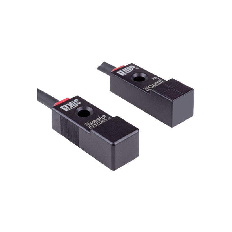
A typical proximity sensor wiring diagram includes several key components. First is the sensor itself, which has three or four wires depending on its type (PNP or NPN, and normally open or normally closed). The power supply, usually 10-30V DC for most industrial DC sensors, provides the necessary operating voltage. The load, often the input module of a PLC, a relay coil, or an indicator lamp, is the device controlled by the sensor's output. Protective devices like fuses or circuit breakers are also shown to safeguard the circuit. The diagram clearly labels each wire: brown typically for positive DC supply (+V), blue for common negative or DC 0V, and black (or sometimes white) for the switched output signal. A proper diagram will also indicate the sensor's sensing range and any required load current specifications.
Wiring a 3-Wire DC PNP Proximity Sensor
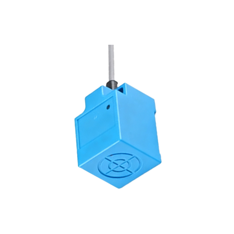
The PNP (sourcing) sensor is one of the most common types. In its wiring diagram, the brown wire connects to the positive terminal of the DC power supply. The blue wire connects to the negative terminal (0V) of the power supply and also to one side of the load. The black (output) wire connects to the other side of the load. When the sensor detects an object, it switches the output, connecting the black wire internally to the positive supply (brown wire). This action sources current from the supply, through the sensor's output, to the load, and back to the supply's negative via the blue wire connection, thus energizing the load. This configuration is often described as "load connected between output and negative." The diagram should clearly show this path and typically include the PLC input symbol to illustrate a complete circuit.
Wiring a 3-Wire DC NPN Proximity Sensor
Conversely, the NPN (sinking) sensor has a different current path. The wiring for power remains identical: brown to positive, blue to negative. However, for the load connection, one side of the load is connected to the positive supply rail. The other side of the load is connected to the black (output) wire of the sensor. When activated, the NPN sensor switches its output internally to connect the black wire to the negative supply (blue wire). This sinks current from the positive supply, through the load, into the sensor's output, and back to the negative terminal. This is summarized as "load connected between positive and output." It is critical to match the sensor's type (PNP or NPN) with the PLC input module's expected sinking or sourcing configuration to avoid malfunction or damage.
Interfacing with PLCs and Relays
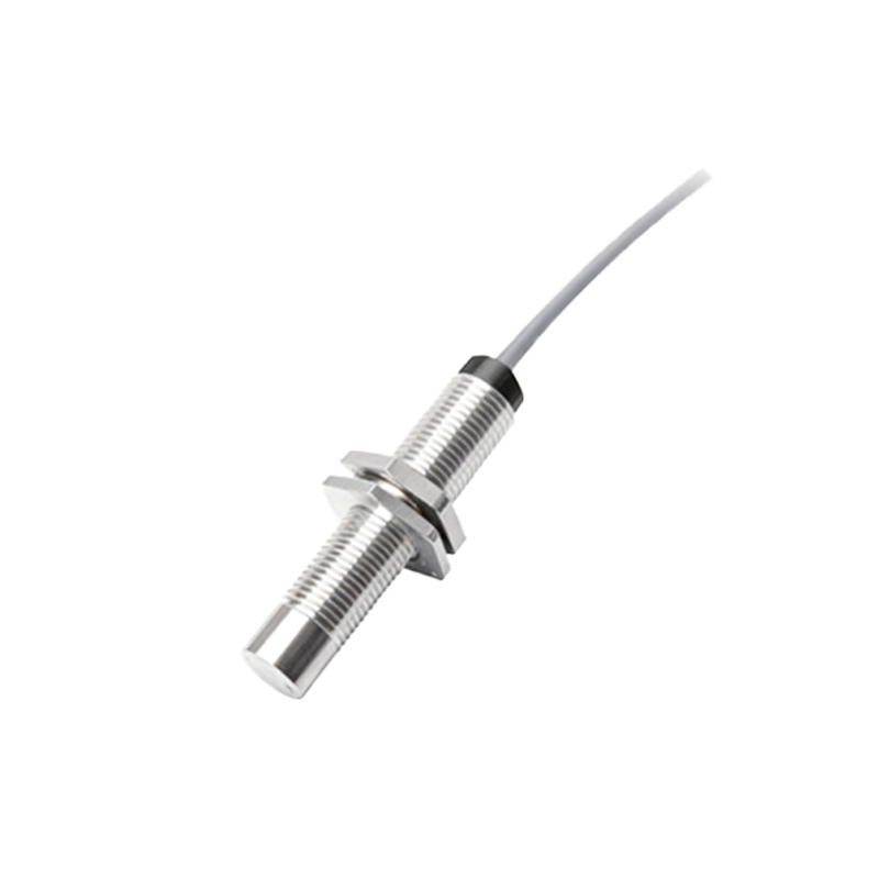
Wiring diagrams become especially important when connecting sensors to PLCs or relays. For a PNP sensor connected to a PLC sinking input module, the PLC's common input point is connected to 0V. The sensor's output wire connects directly to the specific PLC input channel. When the sensor activates, it provides a positive voltage signal to the PLC input. For an NPN sensor with a PLC sourcing input module, the PLC common is connected to +V, and the sensor provides a path to 0V. When using relays, the sensor's output typically drives the relay coil. The diagram must account for the coil's voltage and current ratings, and often includes a flyback diode across the relay coil to suppress voltage spikes generated when the coil is de-energized, protecting the sensor's solid-state output.
Shielded Cabling and Noise Reduction Techniques
Industrial environments are prone to electrical noise from motors, drives, and other equipment, which can cause false triggering of sensitive proximity sensors. A proper wiring diagram should incorporate best practices for noise immunity. This includes using shielded cables for sensor connections. The diagram should indicate that the cable shield is grounded at only one