Introduction to Inductive Proximity Sensors
Inductive proximity sensors are fundamental components in industrial automation, renowned for their non-contact detection of metallic objects. Operating on the principle of electromagnetic induction, these sensors generate an oscillating electromagnetic field from a coil. When a metallic target enters this field, eddy currents are induced on the target's surface. This action dampens the oscillation amplitude of the sensor's internal LC tank circuit. The sensor's electronics detect this change in oscillation, process the signal, and trigger a solid-state output switch. This robust and wear-free operation makes them ideal for harsh environments with presence of dirt, oil, or vibrations, where mechanical switches would fail. Their primary applications include position sensing, limit switching, counting, and speed detection on conveyor systems, machine tools, and robotic cells.
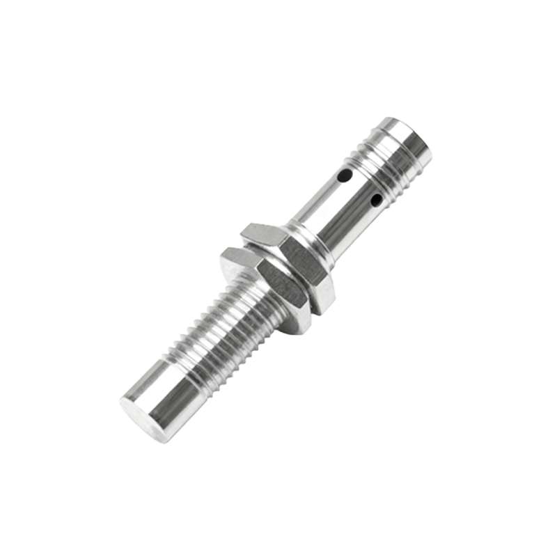
Core Components and Circuit Architecture

The heart of an inductive proximity sensor is its oscillator circuit, typically a Colpitts or Hartley oscillator configuration centered around an inductor (the sensing coil) and capacitors forming the resonant LC tank. This oscillator runs at a high frequency, often between 100 kHz and 1 MHz. The coil is wound on a ferrite core to concentrate the electromagnetic field at the sensor's active face. In parallel, a demodulator circuit rectifies the high-frequency AC signal from the oscillator. A Schmitt trigger or a comparator stage then evaluates the demodulated signal level against a predefined threshold. Once the damping caused by a target exceeds this threshold, the output driver stage—usually consisting of a transistor (for NPN/PNP outputs) or a solid-state relay—is activated. A stable DC power supply, often with reverse polarity protection and voltage regulation, powers all these stages.
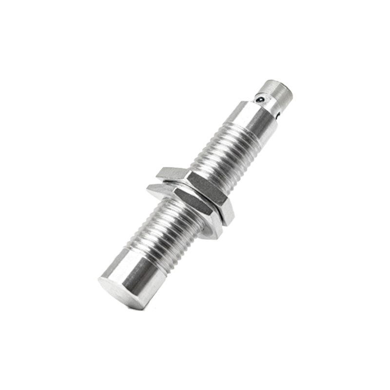
Detailed Circuit Diagram Analysis
A standard three-wire DC sensor circuit diagram reveals the internal topology. The positive supply (V+, typically 10-30V DC) and negative (0V) lines power the circuit. An integrated voltage regulator ensures stable voltage for the oscillator and logic ICs. The LC tank circuit (L1 and C1) is connected to the oscillator transistor (Q1). The signal from the collector of Q1 is fed to a demodulation network (D1, C2). The resulting DC voltage is applied to the inverting input of a comparator (IC1). A voltage divider network sets a precise reference voltage at the non-inverting input. When no target is present, the demodulated voltage is higher than the reference, keeping the comparator output low. A metallic target dampens the oscillation, causing the demodulated voltage to drop below the reference, flipping the comparator output high. This signal then drives the base of the output transistor (Q2), allowing current to flow from the output pin to the common (sinking/NPN) or from the supply to the output pin (sourcing/PNP).
Output Configuration Considerations
Understanding the output circuit is crucial for proper integration. The two primary types are NPN (sinking) and PNP (sourcing) transistor outputs. In an NPN circuit diagram, the load (e.g., a PLC input) is connected between the sensor's output wire and the positive supply (V+). The NPN output transistor sinks current to 0V when active. Conversely, in a PNP diagram, the load is connected between the output and 0V, and the PNP transistor sources current from V+. Many modern sensors also feature a Normally Open (NO) or Normally Closed (NC) logic, which is implemented in the switching logic before the output stage. Some advanced models include short-circuit protection, overload protection, and status indication LEDs within the output stage, which are visible as additional components like series resistors and Zener diodes in the schematic.
Shielded vs. Unshielded Sensor Designs
The physical construction and its representation in the magnetic field diagram significantly impact performance. Shielded (flush-mountable) sensors have a metallic ring surrounding the coil, which focuses the electromagnetic field radially in front of the sensor. This allows them to be mounted flush in metal without triggering false signals from the surrounding material. Unshielded (non-flush) sensors lack this shield, resulting in a larger, more lateral field. They offer a longer sensing range but cannot be mounted flush in metal. This design choice affects the equivalent circuit model, as the shielding introduces additional parasitic capacitance and affects the inductance value, which the oscillator circuit must be tuned to accommodate for stable operation.
Design Tips for Reliability and Noise Immunity
To ensure reliable operation in electrically noisy industrial environments, the circuit design must incorporate several key features. Proper filtering on the power supply lines, using a combination of capacitors and sometimes an inductor, is essential to suppress