Understanding Proximity Sensor Fundamentals
Proximity sensors are indispensable components in modern industrial automation, detecting the presence or absence of an object without physical contact. The selection process begins with a solid grasp of the core technologies. Inductive sensors are the workhorses for detecting metallic objects, utilizing an electromagnetic field. Capacitive sensors, on the other hand, can detect a wider range of materials, including liquids, powders, and non-metals, by measuring changes in capacitance. Ultrasonic sensors use sound waves to detect objects and measure distance, making them suitable for challenging environments with dust or vapor. Finally, photoelectric sensors employ a light beam, offering the longest sensing ranges and versatility for various surface types. Understanding these fundamental operating principles is the critical first step in narrowing down your model choices.
Defining Your Application Requirements
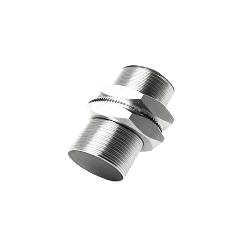
A precise definition of the application is paramount. Start by identifying the target object's material composition, size, and shape. For a small metal bolt, an inductive sensor is ideal. For a glass bottle on a conveyor, a photoelectric or capacitive sensor is necessary. Next, determine the required sensing distance or range. Always consider the manufacturer's rated operating distance and apply a safety factor, typically 70-80% of the nominal value, to ensure reliable operation under real-world conditions like voltage fluctuations or temperature changes. The physical installation environment demands careful scrutiny. Will the sensor be exposed to extreme temperatures, heavy washdowns, oils, coolants, or intense vibration? These factors directly dictate the required housing material (e.g., stainless steel for corrosive settings), ingress protection (IP) rating, and overall robustness.
Evaluating Electrical and Output Specifications
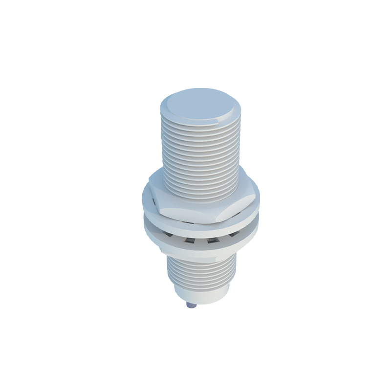
The electrical characteristics of the sensor must seamlessly integrate with your control system. First, match the supply voltage (e.g., 10-30V DC, 20-250V AC) to your available power source. The output type is a crucial decision point. Two-wire sensors are simple to wire but have inherent leakage current. Three-wire sensors (PNP or NNP sourcing) and four-wire versions offer more precise switching and are standard in DC systems. You must choose between a normally open (NO) or normally closed (NC) contact configuration based on the safety and logic requirements of your circuit. Don't overlook the output current rating; it must be sufficient to drive the connected load, such as a PLC input or a relay coil. For high-speed applications like counting or encoder feedback, verify the sensor's switching frequency to ensure it can keep pace.
Considering Physical Form and Mounting
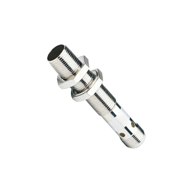
The sensor's housing shape and size are often constrained by the mechanical design of the machine. Cylindrical sensors (e.g., M8, M12, M18, M30 threads) are common and easy to install in drilled holes. Rectangular or block-style sensors offer flexibility for surface mounting. Factors like flush-mountable or non-flush mount designs significantly affect the sensing range and installation space. Flush-mounted inductive sensors can be embedded in metal without interference but have a shorter range. Ensure there is adequate clearance around the sensor head for the magnetic or ultrasonic field to propagate correctly. The connection method—integral cable or quick-disconnect (QD) connector—impacts maintenance and replacement ease. QD connectors facilitate swift sensor swaps but require proper strain relief.
Accounting for Special Features and Standards
Beyond basic functionality, several advanced features can optimize performance. For inductive sensors, the ability to detect different metals (e.g., steel, aluminum, copper) at a consistent range may require a factor-1 or factor-1 universal model. Temperature compensation is vital in environments with wide thermal swings. In safety-critical applications, sensors with built-in diagnostics, short-circuit protection, and reverse polarity protection enhance system reliability and prevent downtime. Always verify compliance with relevant industry standards and certifications, such as ATEX or IECEx for hazardous areas, UL, or CE marking for regional market access. These certifications are not optional in regulated industries.
Finalizing Selection and Implementation
With all parameters defined, use manufacturer selection guides, online configurators, or consult with technical support to shortlist specific part numbers. Request detailed datasheets and compare key specifications side-by-side. Where possible, obtain a sample unit for real-world testing under actual operating conditions. This final validation step can reveal unforeseen issues with target material, environmental noise, or mounting alignment. Proper installation is as important as the selection itself. Follow the manufacturer's guidelines for mounting torque, cable routing, and maintaining the correct sensing gap. A systematic approach—from understanding fundamentals to practical validation—ensures the selected proximity sensor model delivers reliable, long-term performance in your specific application.