Introduction to Magnetic Proximity Sensors
Magnetic proximity sensors are fundamental components in modern industrial automation and control systems. These non-contact devices detect the presence or absence of a magnetic field, typically generated by a permanent magnet or an electromagnet. Their operation relies on the principle of magnetic field interaction with a sensing element, which triggers a change in electrical output. Unlike mechanical limit switches, they offer superior reliability, longer operational life, and the ability to function in harsh environments with dust, oil, or moisture. Common applications include position sensing in machinery, speed detection in conveyor systems, and safety interlocking in automated processes. The core value proposition lies in their robustness, maintenance-free operation, and precise, repeatable detection without physical contact.
Core Components and Material Selection
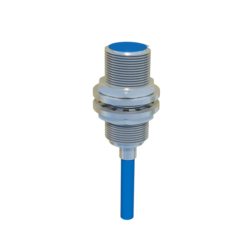
The manufacturing process begins with the careful selection of high-quality materials. The key internal components are the sensing element, the magnet, and the housing. The sensing element is most often a reed switch or a Hall-effect integrated circuit (IC). Reed switches, consisting of two ferromagnetic reeds sealed in a glass envelope, are chosen for their simplicity and low power consumption in basic applications. For more advanced requirements, Hall-effect ICs are preferred. These semiconductor devices provide digital or analog output, higher switching frequencies, and greater sensitivity with programmable features. The magnet, usually a rare-earth type like neodymium for its strong magnetic field, is selected based on the required sensing distance and environmental conditions. The housing, typically made from stainless steel, brass, or engineered plastics like PBT or PPS, provides environmental protection (IP ratings), mechanical strength, and shielding from external electromagnetic interference.
The Printed Circuit Board Assembly Process
For sensors utilizing Hall-effect ICs or other active electronics, the Printed Circuit Board (PCB) is the central nervous system. The process starts with a fabricated PCB, often with a conformal coating specified for industrial use. Surface Mount Technology (SMT) lines place miniature components like resistors, capacitors, and the Hall-effect IC onto the board with extreme precision. Reflow soldering then creates permanent electrical connections. For sensors incorporating reed switches, they are often wave-soldered or manually soldered to the PCB or directly to lead wires. Rigorous in-line Automated Optical Inspection (AOI) checks for soldering defects, component placement accuracy, and board integrity. This stage is critical for ensuring the long-term electrical reliability of the sensor.
Encapsulation and Housing Assembly
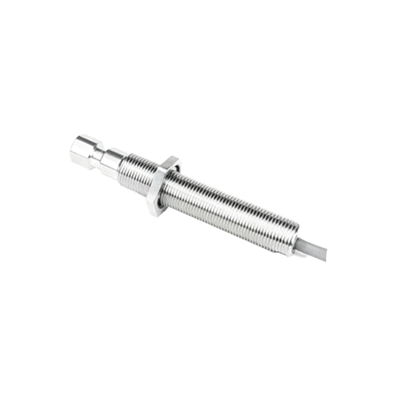
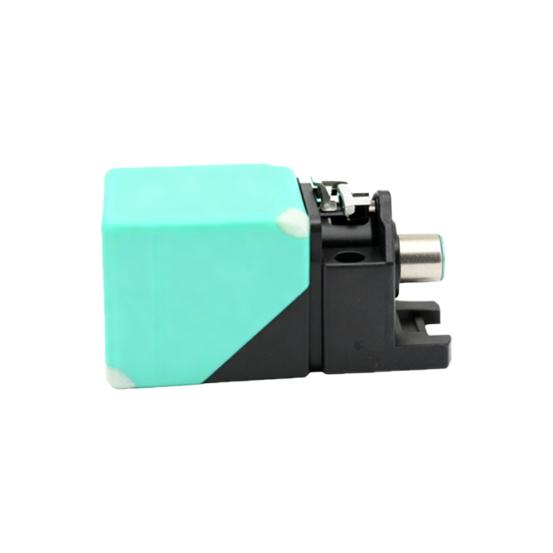
After PCB assembly, the sensitive electronics must be protected. This is achieved through a process called potting or encapsulation. The PCB assembly is placed into the sensor housing, and a liquid potting compound, usually an epoxy or polyurethane resin, is carefully dispensed. This compound cures to form a solid, protective block that immobilizes components, provides exceptional resistance to vibration and shock, and creates a hermetic seal against moisture, chemicals, and contaminants. Following encapsulation, the housing is sealed. This may involve laser welding for metal housings, ultrasonic welding for plastics, or threading and sealing with O-rings and gaskets. The choice of sealing method directly impacts the sensor's Ingress Protection (IP) rating, which is a key selling point for industrial applications.
Calibration and Functional Testing
No sensor leaves the production floor without undergoing stringent calibration and testing. Each unit is subjected to a battery of automated tests. Key parameters verified include the operating point (the distance at which the sensor switches in the presence of the target magnet), the release point, and the resulting hysteresis. The switching frequency response is tested for dynamic applications. Electrical tests check for correct output signal (PNP/NPN, NO/NC), current consumption, and protection against reverse polarity and short circuits. Environmental stress screening, such as temperature cycling and vibration tests, may be performed on sample batches to validate design robustness. This phase ensures every sensor meets the precise specifications and performs reliably under defined conditions.
Quality Assurance and Final Packaging
Quality assurance is integrated throughout the manufacturing lifecycle. Statistical Process Control (SPC) monitors critical production parameters to identify and correct process deviations in real-time. Finished sensors undergo a final visual inspection and are often marked with laser engraving for part numbers, date codes, and electrical symbols. They are then packaged according to customer requirements, which may involve individual boxes, blister packs, or bulk packaging for automated assembly lines. Documentation, including datasheets and certificates of conformity, accompanies each shipment. Adherence to international standards like ISO 9001 for quality management and relevant IEC standards for electrical safety is paramount for manufacturers serving global markets.
Industry Trends and Future Outlook
The magnetic proximity sensor industry continues to evolve. Key trends include miniaturization, enabling sensors to