Proximity sensors are ubiquitous in modern technology, silently enabling countless functions in our smartphones, industrial machinery, and automotive systems. While their operation is often taken for granted, understanding their internal structure is key to appreciating their capabilities and applications. This article delves into the anatomy of a typical proximity sensor, breaking down its components as illustrated in a standard cross-sectional diagram.
At the heart of most proximity sensors lies the sensing element. In inductive sensors, this is a coil wound around a ferrite core, which generates an oscillating electromagnetic field. Capacitive sensors feature conductive plates that create an electrostatic field. Photoelectric sensors, another common type, contain an infrared Light Emitting Diode (LED) as the emitter. Directly adjacent to this emitter is the photodetector, typically a phototransistor or photodiode, which is critically sensitive to the specific wavelength of light emitted by the LED. This precise pairing ensures the detector ignores ambient light interference.
Surrounding these core elements is the sensor housing or body. This casing, usually made from robust materials like nickel-plated brass, stainless steel, or engineered plastics (PBT, PPS), serves multiple vital functions. It provides mechanical protection for the delicate internal components from physical impact, vibration, and environmental hazards. The housing also acts as a shield, containing the sensor's field (electromagnetic or electrostatic) to define its effective sensing range and directionality, preventing erratic behavior. The front face of the housing is the sensing face, often made of a material that allows the relevant field (magnetic, electric, or infrared light) to pass through unimpeded.
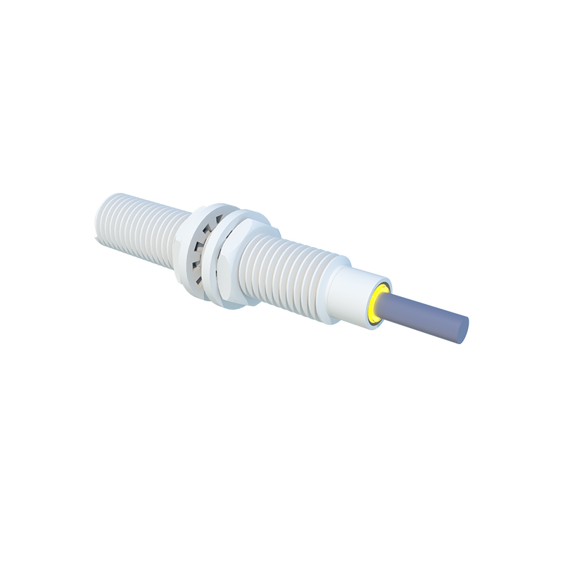
Embedded within the housing is the signal processing circuitry. This is the "brain" of the sensor. It typically includes an oscillator circuit to generate the high-frequency field for inductive/capacitive types, an amplifier to boost the often-weak signal received from the detector, and a comparator or threshold circuit. This comparator constantly evaluates the received signal against a predefined reference level. When a target object enters the sensing field, it causes a detectable change—damping the oscillation, altering capacitance, or reflecting light back to the detector. The circuitry converts this analog change into a clean, digital output signal.
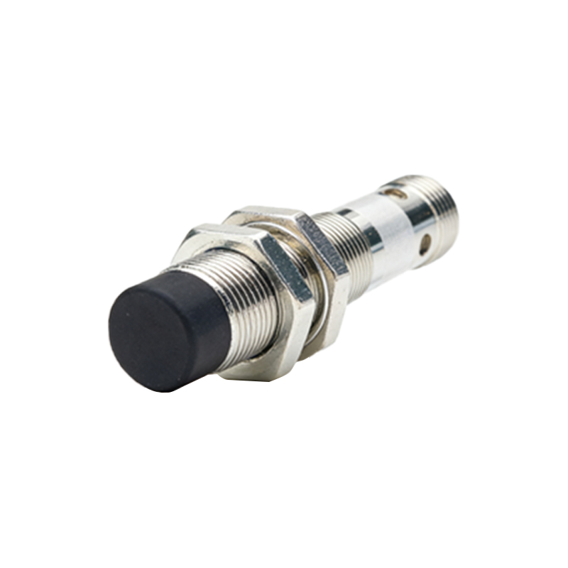
The output stage is where the sensor interfaces with the larger control system, such as a Programmable Logic Controller (PLC). Common output types include NPN (sinking) or PNP (sourcing) transistors for a digital on/off signal, analog voltage (0-10V), or analog current (4-20mA) for distance-proportional information. These components are connected to the sensor's electrical terminals or a pre-attached cable. For sensors requiring connection to a network, additional communication chips (for IO-Link, for instance) may be present on the circuit board.
Finally, the diagram often includes indicators, such as a Light Emitting Diode (LED). This LED provides vital visual feedback, illuminating when the sensor is powered and often changing state (e.g., from green to yellow) when an object is detected, greatly aiding in installation, troubleshooting, and operational verification.
In summary, a proximity sensor is a sophisticated integration of field generation, precise detection, intelligent signal conditioning, and robust packaging. Each component in the anatomical diagram, from the emitter/detector pair to the housing and output transistor, plays a specific role in achieving reliable, non-contact detection. Understanding this anatomy empowers engineers and technicians to select the right sensor for the application, optimize its performance, and diagnose issues effectively, ensuring seamless operation in automated systems.