Inductive proximity sensors are a cornerstone of modern industrial automation, offering non-contact detection of metallic objects with remarkable reliability. This experiment guide provides a hands-on approach to understanding their fundamental principles, key characteristics, and practical applications. By building a simple test circuit and conducting systematic measurements, engineers and students can gain invaluable insight into the operational behavior of these ubiquitous devices.
The core principle behind an inductive proximity sensor is electromagnetic induction. The sensor contains a coil wound around a ferrite core, which forms part of an oscillator circuit. When an alternating current flows through this coil, it generates an alternating magnetic field in front of the sensor face. When a metallic target enters this field, eddy currents are induced on the target's surface. These eddy currents draw energy from the oscillator, causing a change in its amplitude. An evaluation circuit within the sensor detects this amplitude drop and triggers a switching signal. For ferrous metals (like iron and steel), an additional effect occurs where the magnetic field is concentrated, further enhancing the sensing distance.
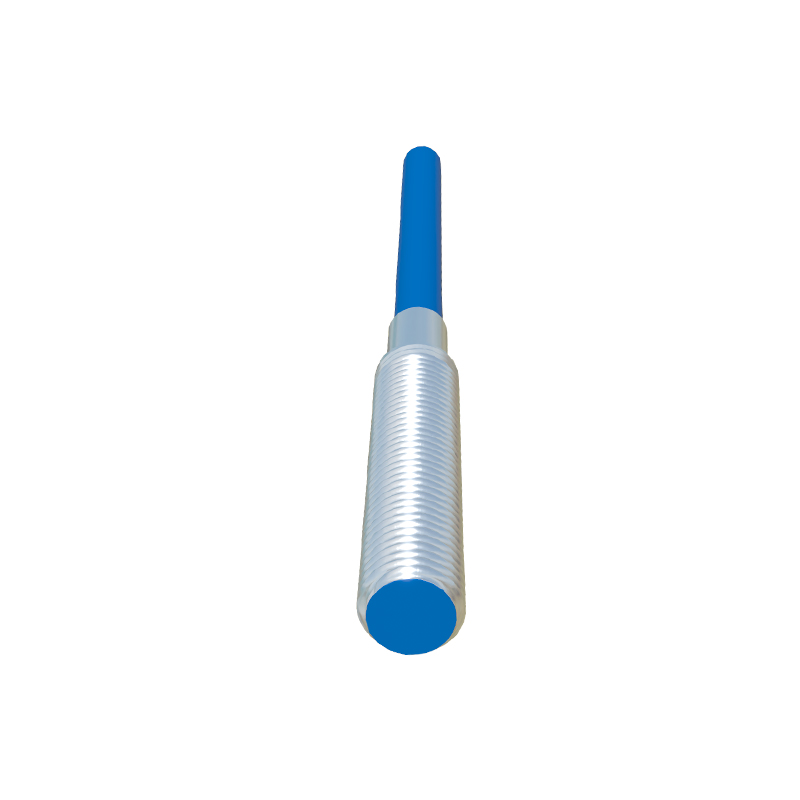
To conduct a basic experiment, you will need the following components: a standard cylindrical inductive proximity sensor (e.g., 12-24V DC, normally open type), a regulated DC power supply, a multimeter, a set of metal test targets (steel, aluminum, brass, copper plates of the same dimensions), a non-metallic spacer, and connecting wires. Begin by constructing the circuit. Connect the brown wire of the sensor to the positive terminal of the power supply and the blue wire to the negative terminal. Connect the black wire (signal output) to one probe of the multimeter set to measure DC voltage, with the other probe connected to the power supply's negative terminal. Ensure all connections are secure before powering the circuit.
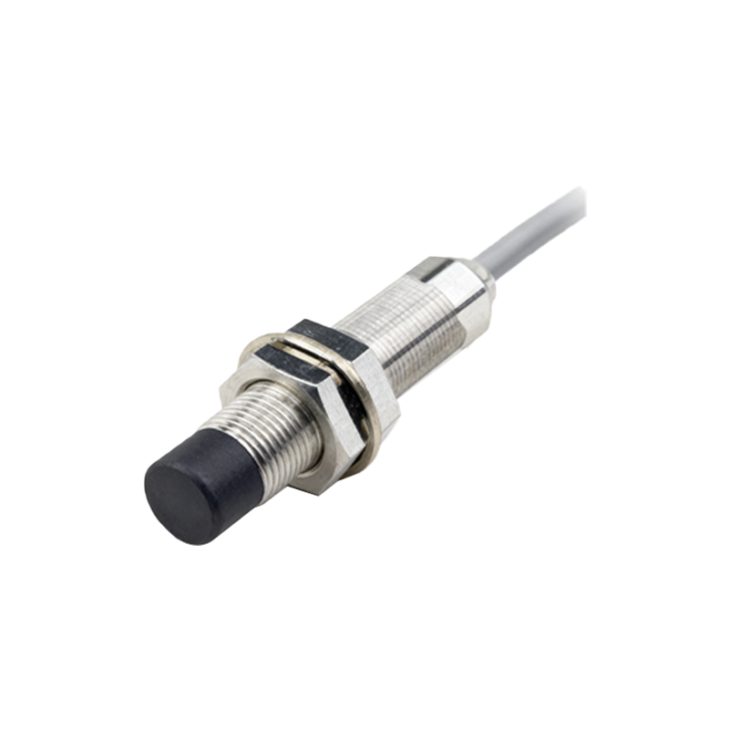
The first experiment measures the sensor's nominal sensing distance (Sn). This is the guaranteed operating distance under standardized conditions, typically with a mild steel target. Mount the sensor securely. Using the non-metallic spacer, slowly bring a standard mild steel target (1mm thick, square side length equal to the sensor's diameter or three times the nominal sensing distance, whichever is larger) towards the sensor face axially. The exact point where the sensor's output LED turns on and the multimeter shows a voltage switch (from 0V to near supply voltage for a PNP type) marks the actual sensing point. Measure this distance carefully. Compare it to the Sn value listed in the sensor's datasheet. Note that environmental factors like temperature and voltage tolerances can cause slight deviations.
A critical characteristic is the influence of target material. Repeat the distance measurement procedure with identical-sized targets made of stainless steel, aluminum, brass, and copper. You will observe a significant reduction in the effective sensing distance for non-ferrous metals. This is quantified by a reduction factor. For instance, if the sensor detects mild steel at 10mm and aluminum at 5mm, the reduction factor for aluminum is 0.5. This experiment highlights the importance of material specification in application design. Always consult the sensor's datasheet for specific reduction factors.
Next, investigate the hysteresis phenomenon. Hysteresis is the difference between the switch-on point (as the target approaches) and the switch-off point (as the target recedes). It prevents output chatter when a target is positioned exactly at the sensing edge. To measure it, slowly move the steel target towards the sensor until it activates, and note the distance (Switch-On Point). Then, slowly move the target away until the output deactivates, and note this new, larger distance (Switch-Off Point). The difference is the hysteresis, typically 3-10% of the nominal sensing distance. This built-in feature ensures stable switching.
The experiment can be extended to examine the sensor's repeatability. Position a target to trigger the sensor at a fixed distance. Remove and re-insert the target multiple times (e.g., 50 cycles), measuring the variation in the switch-on point. High-quality sensors exhibit minimal deviation, often within 1-2% of Sn. Furthermore, test the sensor's response to different target shapes and orientations. A larger target surface generally provides a more consistent signal, while sensing the edge or a small bolt head will reduce the effective range.
Finally, explore a simple application simulation. Use the sensor's output to control an LED or a small relay. This demonstrates its role as a primary input device in a control system, such as detecting the presence of a metal part on a conveyor or counting rotating gear teeth. Always ensure the operating voltage and current ratings of the sensor and load are compatible.
Through these methodical experiments, the robust and material-dependent nature of inductive proximity sensors becomes clear. They are immune to dust, dirt, and non-metallic contaminants, making them ideal for harsh industrial environments. However, their limitation to metallic objects and the variation in