Distance laser sensors are critical components in modern industrial automation, offering high-precision, non-contact measurement for applications ranging from positioning and inspection to safety and quality control. However, like all sophisticated electronic devices, they are susceptible to performance degradation or failure due to environmental factors, mechanical stress, or component aging. Proper maintenance and systematic troubleshooting are essential to ensure operational reliability, minimize downtime, and extend sensor lifespan. This guide outlines key maintenance practices and a step-by-step troubleshooting methodology for engineers and technicians.
Preventive Maintenance Best Practices
Regular preventive maintenance is the first line of defense against unexpected sensor failure. Establish a scheduled maintenance routine based on the sensor's operational hours and environmental conditions. The core practice is keeping the optical components impeccably clean. The laser emitter and receiver lenses are vulnerable to contamination from dust, oil mist, moisture, or process debris. Use only approved, lint-free wipes and optical-grade cleaning solutions. Never use abrasive materials or aggressive chemicals that could scratch or coat the lens, permanently affecting accuracy. Inspect the sensor housing and mounting bracket for physical integrity. Ensure all fasteners are tight to prevent misalignment from vibration, which is a common cause of erratic readings. Verify the stability of the power supply; voltage spikes or ripple can damage internal circuitry. For sensors in harsh environments, confirm that protective accessories like air purgers or protective windows are functioning correctly and are themselves clean.
Common Failure Symptoms and Initial Checks
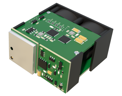
When a distance laser sensor malfunctions, symptoms typically manifest as unstable readings, a complete loss of signal, consistent offset errors, or communication failures with the PLC. Before delving into complex diagnostics, perform these initial checks:
1. Power and Connections: Verify the supply voltage is within the sensor's specified range using a multimeter. Inspect the cable and connectors for damage, wear, or loose terminals. A intermittent connection often causes flickering output.

2. Environmental Conditions: Check for new sources of optical interference, such as intense ambient light (sunlight, welding arcs), highly reflective surfaces in the measurement path, or the presence of steam or smoke. Ensure the sensor's operating temperature and humidity are within specifications.
3. Target Properties: Confirm that the target material, color, surface texture, and size still meet the sensor's requirements. A sudden change, like a shift from a matte white to a glossy black surface, can significantly affect performance.
Systematic Troubleshooting Procedure
If initial checks do not resolve the issue, follow a structured diagnostic approach:
* Step 1: Isolation Test. If possible, remove the sensor from the machine and test it in a controlled bench setup. Use a known, stable target at a fixed distance. This eliminates external machine and process variables.
* Step 2: Parameter Verification and Reset. Access the sensor's configuration (via teach-in button, potentiometer, or software). Document the current settings, then perform a factory reset. Reconfigure basic parameters according to the datasheet. A corrupted configuration file is a common software-related fault.
* Step 3: Output Signal Analysis. Monitor the sensor's output signal (analog 4-20mA/0-10V or digital) with an oscilloscope or a high-resolution multimeter. Look for noise, instability, or a signal that does not scale correctly with target distance changes. Compare findings with expected behavior from the manual.
* Step 4: Substitution. The most definitive hardware test is swapping the suspect sensor with a known-good unit of the same model under identical conditions. If the problem is resolved, the original sensor is faulty.
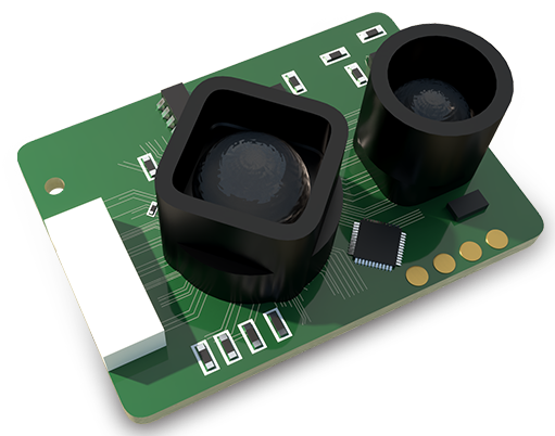
* Step 5: Internal Inspection (Advanced). For major failures, internal inspection may be necessary. Warning: This may void warranties and should only be done by qualified personnel with ESD protection. Look for signs of burnt components, cracked solder joints, or moisture ingress on the PCB. The laser diode itself can degrade over time, leading to reduced output power.
When to Repair vs. Replace
Economic and technical considerations dictate the repair-or-replace decision. Minor issues like dirty lenses, loose cables, or incorrect settings are easily repairable. However, internal damage to the laser diode, detector array, or core processing board often requires specialized calibration equipment that makes field repair impractical. For critical processes where calibration traceability and maximum reliability are paramount, replacement with a new or factory-reconditioned unit is usually the recommended course of action. Always consult the manufacturer's technical support with error codes and diagnostic data before deeming a sensor irreparable.
In conclusion, a proactive maintenance culture combined with a logical, step-by-step troubleshooting process is key to managing distance laser sensor performance. Keeping optics clean, ensuring stable electrical and mechanical installation, and understanding the sensor's limitations in the application environment will prevent the majority of issues. When failures occur, systematic isolation and testing will quickly identify the root cause, enabling informed decisions to restore system functionality efficiently.