In the realm of industrial automation, robotics, and precision engineering, laser distance sensors are indispensable tools. Their ability to provide non-contact, high-speed, and high-accuracy measurements makes them the preferred choice for countless applications, from quality control on assembly lines to the navigation of autonomous vehicles. However, a persistent challenge that engineers and technicians frequently encounter is measurement fluctuation or instability. These seemingly random variations in the reported distance can compromise system reliability, reduce yield, and lead to costly errors. This article delves into the root causes of laser sensor distance measurement fluctuations and outlines practical strategies for mitigation.
At its core, a typical time-of-flight (ToF) or phase-shift laser sensor calculates distance by measuring the time it takes for a laser pulse to travel to a target and back, or by analyzing the phase shift of a modulated laser beam. Any factor that interferes with this process can introduce noise and cause fluctuations. The primary culprits can be categorized into environmental, target-related, and sensor-intrinsic factors.
Environmental Factors: The Invisible Interference
The operating environment is a major source of measurement noise.
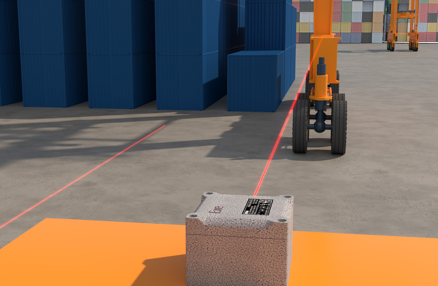
* Ambient Light: Intense ambient light, especially from sources like direct sunlight, halogen lamps, or other lasers operating at similar wavelengths, can flood the sensor's photodetector. This creates a high background noise level, making it difficult for the sensor to distinguish the weak return signal from its own laser, leading to erratic readings or complete signal loss.
* Atmospheric Conditions: Particles in the air, such as dust, smoke, steam, or fog, can scatter and attenuate the laser beam. This scattering reduces the signal strength returning to the sensor and can create false signals from the particles themselves, causing the measured distance to jump between the target and the interfering particle.
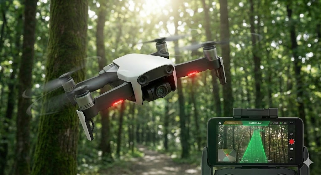
* Air Turbulence and Temperature Gradients: Variations in air density caused by heat sources, moving machinery, or ventilation systems can slightly bend the laser beam (a phenomenon similar to a mirage). This atmospheric refraction can alter the effective path length of the beam, introducing small but significant fluctuations, particularly over longer distances.
* Vibration: Mechanical vibration of either the sensor mounting or the target itself can cause the laser spot to move microscopically on the target surface. If the surface is not perfectly uniform, this movement can change the nature of the reflected signal, manifesting as measurement jitter.
Target-Related Factors: It's Not Just About Distance
The characteristics of the target object are equally critical.
* Surface Properties: The color, roughness, and material of the target dramatically affect reflectivity. A dark, matte, or absorptive surface (like black rubber or velvet) returns a very weak signal, pushing the sensor towards its signal-to-noise ratio limit and resulting in noisy data. Conversely, a specular or mirror-like surface can reflect the beam away from the sensor, causing a drop-out, or create multiple reflection paths that confuse the sensor's timing circuitry.
* Surface Angle (Incidence Angle): As the angle between the laser beam and the target surface normal increases, the effective reflectivity back to the sensor decreases. Beyond the sensor's specified maximum incidence angle, the signal may become too weak for a stable measurement.
* Target Transparency or Translucency: Measuring the distance to glass, clear plastics, or liquids is notoriously difficult. The laser beam may partially reflect from the front surface, partially transmit through the material, and reflect from a rear surface or background object. The sensor may lock onto any of these reflections, causing large, unpredictable jumps in the measured value.
Sensor-Intrinsic and Setup Factors
Finally, issues can arise from the sensor itself or its configuration.
* Electrical Noise: Electromagnetic interference (EMI) from nearby motors, drives, welders, or high-frequency equipment can be inductively or capacitively coupled into the sensor's signal lines or power supply, corrupting the delicate timing or analog signals.
* Insufficient Sampling/Averaging: Most sensors offer configurable digital filtering or averaging functions. If the sensor is set to output raw, unaveraged data at a high speed, the inherent noise of any physical measurement will be fully visible as fluctuation. This is often a simple configuration oversight.
* Optical Contamination: Dust, oil, or condensation on the sensor's transmitter or receiver lens will attenuate both the outgoing and incoming light, degrading performance and increasing noise.
* Sensor Limitations: Operating outside the specified measurement range, using a spot size that is too large for the target feature, or exceeding the maximum allowable measurement rate can all lead to unstable outputs.
Mitigation Strategies for Stable Measurements
Addressing fluctuations requires a systematic approach:
1. Environmental Control: Shield the sensor and target from strong ambient light using physical shrouds or filters. Install protective air knives or purging systems to keep lenses clean and clear of dust or mist in dirty environments. Isolate the sensor from sources of vibration using dampening mounts.
2. Target Preparation: When possible, optimize the target. Apply a retro-reflective tape or a matte white paint patch to provide a consistent, high-return surface. Ensure the target is presented at an angle within the sensor's specifications.
3. Sensor Selection and Configuration: Choose a sensor with a wavelength and power rating suitable for the environment (e.g., blue lasers perform better in sunlight than red). Select a model with a high resistance to ambient light and EMI. Crucially, configure the internal filtering correctly—increase the moving average or digital filter settings to smooth out high-frequency noise at the expense of a slightly slower response time.
4. Electrical and Mechanical Best Practices: Use shielded, twisted-pair cables for signal transmission and ground them properly at one end. Separate sensor cables from power lines. Ensure a stable, clean power supply. Mount the sensor rigidly on a stable platform.
5. Advanced Techniques: For transparent targets, use a specialized sensor with background suppression or a triangulation-based sensor configured to ignore the secondary reflection. For extremely unstable signals, post-processing the data stream with a more advanced statistical filter (like a Kalman filter) in the PLC or controller can often extract a stable trend from the noisy raw data.
In conclusion, laser sensor distance fluctuations are not an inherent flaw but a diagnosable symptom of system-environment interaction. By methodically analyzing the environmental conditions, target properties, and sensor setup, engineers can identify the interference source and apply the appropriate corrective measures. A deep understanding of these principles is key to unlocking the full potential of laser measurement technology, ensuring the high levels of precision and reliability demanded by modern industrial applications.