Proximity sensors are indispensable components in modern industrial automation, robotics, and safety systems. Their ability to detect the presence or absence of an object without physical contact ensures reliability, longevity, and precision in countless applications. Understanding the underlying sensing principles is crucial for proper selection, installation, and troubleshooting. This article provides a detailed, diagram-centric explanation of the core operating principles of the main proximity sensor types: inductive, capacitive, and photoelectric.
1. Inductive Proximity Sensors: Detecting Metallic Objects
The fundamental principle of an inductive proximity sensor is electromagnetic induction. The core component is a coil wound around a ferrite core, which forms part of an oscillator circuit (typically LC or RC). When an alternating current is passed through this coil, it generates an alternating electromagnetic field in front of the sensor's active face.
Sensing Principle Diagram & Process:
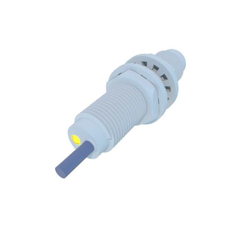
Diagram Element A (Oscillator): Shows the internal oscillator circuit generating a high-frequency electromagnetic field at the sensing face.
Diagram Element B (Electromagnetic Field Lines): Illustrates the field radiating from the sensor head.
Diagram Element C (Target Object): A metallic object (e.g., steel, aluminum, copper) enters this field.
Physical Process: Eddy currents are induced on the surface of the target metal. These currents create their own opposing magnetic field, which loads the oscillator circuit.
Diagram Element D (Signal Processing): This loading effect causes a change in the oscillator's amplitude or frequency. A subsequent trigger circuit (Schmitt trigger) detects this change.
Output: The trigger circuit switches the sensor's solid-state output (PNP/NPN) ON or OFF.
Key characteristics: They only detect metallic targets. Sensing distance depends on the target's material, size, and shape (with standardized correction factors for different metals). They are robust, resistant to environmental factors like dust or oil, and offer high switching frequencies.
2. Capacitive Proximity Sensors: Detecting Nearly Any Material
Capacitive sensors operate on the principle of capacitance change. The sensor face acts as one plate of a capacitor. The target object acts as the second plate, with the air gap as the dielectric.
Sensing Principle Diagram & Process:
Diagram Element A (Electrode Plate): Shows the sensor's active electrode connected to an internal RC oscillator.
Diagram Element B (Electrical Field): Illustrates the fringing electrostatic field projecting from the electrode.
Diagram Element C (Target Object): Any material (metal, plastic, wood, liquid, granules) with a dielectric constant different from air enters this field.
Physical Process: The presence of the target object changes the dielectric constant of the space between the plates, thereby altering the capacitance of the system.
Diagram Element D (Oscillator & Detector): The change in capacitance affects the RC oscillator's amplitude. When the amplitude reaches a threshold, a detector circuit is activated.
Output: The detector circuit switches the output state.
Key characteristics: They can detect both conductive and non-conductive materials. Sensitivity is often adjustable to ignore certain materials (like a container wall) and sense the material inside. They are suitable for level detection, powder sensing, and non-metallic object detection.
3. Photoelectric Sensors: Detecting via Light Beam
Photoelectric sensors use light to detect objects. The core principle involves an emitter (light source: LED, laser) and a receiver (phototransistor, photodiode). They are categorized by their optical design: through-beam, retro-reflective, and diffuse-reflective.
Sensing Principle Diagram & Process for Diffuse-Reflective Type (Most Common):
Diagram Element A (Emitter): Shows the integrated LED (often infrared or red) emitting a modulated light pulse to avoid ambient light interference.
Diagram Element B (Receiver): Shows the photodetector positioned next to the emitter.
Diagram Element C (Target Object): An object enters the sensing range.
Physical Process: The emitted light strikes the target object and is diffusely reflected. A portion of this reflected light returns to the receiver.
Diagram Element D (Amplifier & Comparator): The receiver converts the light intensity into an electrical signal. An amplifier boosts this signal, and a comparator evaluates it against a preset threshold.
Output: If the received light intensity exceeds the threshold, the output switches state.
Through-beam sensors have separate emitter and receiver units; detection occurs when the object interrupts the beam. Retro-reflective sensors use a single unit and a reflector; detection occurs when the object blocks the beam to the reflector.
Key characteristics: They