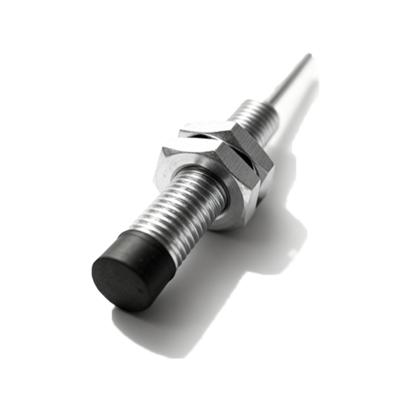
In the realm of industrial automation and motion control, proximity angle sensors are indispensable components for precise angular position detection. This article delves into the fundamental schematic principles of these sensors, providing a detailed analysis for electrical engineering professionals. The core function of a proximity angle sensor is to detect the angular position of a rotating shaft or object without physical contact, typically utilizing inductive, capacitive, or magnetic principles. The most common type in heavy-duty applications is the inductive proximity sensor configured for angular measurement.
A standard schematic for an inductive proximity angle sensor system comprises several key blocks. First is the oscillator circuit, usually based on a Colpitts or Hartley configuration, which generates a high-frequency electromagnetic field from the sensor's active face or a dedicated sensing coil. This oscillator's resonant tank circuit (inductor and capacitors) is crucial; its stability determines sensing accuracy. The sensing element itself is often a specially wound coil or a set of coils arranged around the axis of rotation. The target, typically a metallic cam or a gear-like structure attached to the rotating shaft, modifies the electromagnetic field as it passes. This alteration changes the inductance in the sensing coil, which in turn affects the oscillator's amplitude or frequency.
The next critical stage in the schematic is the demodulator and amplifier. The signal from the oscillator, now modulated by the target's position, is fed into a demodulation circuit (often a simple diode detector or a synchronous demodulator for higher precision) to extract the envelope or the phase shift corresponding to the angular change. This weak DC or low-frequency AC signal is then amplified by an operational amplifier circuit. The gain and bandwidth of this amplifier are carefully selected to match the expected signal range and the required response speed, while filtering out high-frequency noise from the oscillator and environmental interference.
Subsequently, the conditioned analog signal is processed. In modern digital-output sensors, this analog signal is fed into an Analog-to-Digital Converter (ADC) within a microcontroller or a dedicated ASIC. The microcontroller executes algorithms to linearize the signal, as the relationship between the target's angle and the induced signal change is often non-linear. It also handles temperature compensation to counteract drift in the oscillator's components. The output stage is then driven according to the required interface. Common outputs include a Pulse Width Modulation (PWM) signal where the duty cycle is proportional to the angle, a standard analog voltage (0-10V) or current (4-20mA) output, or a digital protocol like IO-Link, SPI, or CANopen for networked systems. The schematic will include output driver transistors or ICs, along with necessary protection components like flyback diodes for inductive loads, TVS diodes for surge protection, and series resistors for current limiting.
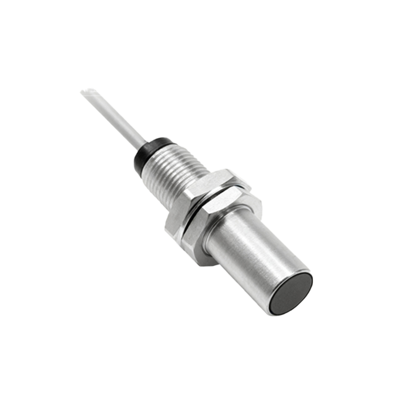
Power supply conditioning is a vital part of the overall schematic. Most industrial sensors operate on a wide-range DC supply (e.g., 10-30V DC). A voltage regulator IC, such as an LDO or a switching regulator, provides stable voltage for the analog and digital cores. Decoupling capacitors are placed strategically near every IC to ensure a clean power rail. Reverse polarity protection, often implemented with a series diode or a MOSFET-based circuit, is almost universally included in industrial sensor schematics.
When analyzing a proximity angle sensor schematic, engineers must pay close attention to the layout of the sensing coils and the grounding scheme. Proper shielding and grounding are paramount to minimize the influence of external electromagnetic interference (EMI) on the sensitive oscillator circuit. A star grounding point is typically used to separate noisy digital grounds from clean analog grounds. Furthermore, the mechanical design of the target (e.g., the shape, size, and material of the gear teeth or cam) is intrinsically linked to the electrical performance. The schematic's effectiveness is validated only when paired with the correct mechanical configuration, which defines the sensor's resolution, repeatability, and linearity.

In conclusion, understanding the schematic of a proximity angle sensor involves a multidisciplinary grasp of oscillator design, analog signal conditioning, digital signal processing, and robust power management. By deconstructing the circuit into these functional blocks—oscillator, demodulator, amplifier, processor, output stage, and power supply—engineers can effectively design, troubleshoot, and integrate these critical sensors into complex automation systems, ensuring reliable and accurate angular feedback for closed-loop control.