Proximity sensors are indispensable components in modern industrial automation, providing non-contact detection of metallic or non-metallic objects. Correct wiring is critical for ensuring reliable operation, safety, and longevity of these sensors. This article provides a detailed, practical guide to proximity sensor wiring, supported by real-world images to illustrate key concepts and common practices.
Understanding the basic types of proximity sensors is the first step. Inductive sensors detect metallic objects, while capacitive sensors can detect both metallic and non-metallic materials. Photoelectric sensors use light beams for detection. Each type has specific wiring requirements, though many share common principles. Most industrial proximity sensors operate on DC (typically 10-30V DC) or AC voltage, and they come in two main output configurations: PNP (sourcing) and NPN (sinking).
Examining a real wiring image of a typical 3-wire DC inductive proximity sensor reveals standard wire colors: brown for positive voltage supply (+V), blue for common negative or ground (0V), and black for the output signal. In a PNP configuration, the black wire outputs a positive voltage when an object is detected. The sensor is powered by connecting brown to +24V DC and blue to 0V DC. The black output wire is then connected to the input terminal of a programmable logic controller (PLC), relay, or other control device. A crucial detail visible in close-up photos is the use of ferrule crimps on stranded wires, which prevent fraying and ensure a secure connection in terminal blocks. Strain relief clamps at the sensor cable entry point are also evident, protecting the electrical connections from physical pull or vibration.
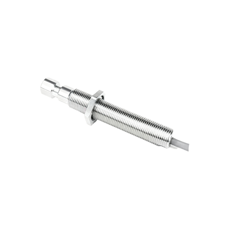
For NPN sensors, the wiring differs fundamentally. Here, the black output wire acts as a sinking path to ground. When the sensor detects a target, it connects the black wire internally to the blue wire (0V). The load (e.g., a PLC input) is connected between the black wire and the positive supply. Real installation images often show clear labeling on the sensor body and wiring diagrams on the datasheet affixed to control cabinet doors, which are vital for maintenance and troubleshooting.
AC-powered proximity sensors, often 2-wire types, are wired in series with the load. A common image shows a brown wire connected to the AC line voltage (e.g., 120V AC) and the blue wire connected to one side of the load, with the load's other side returning to the AC neutral. These sensors are simpler to wire but require careful attention to voltage ratings and load current compatibility.
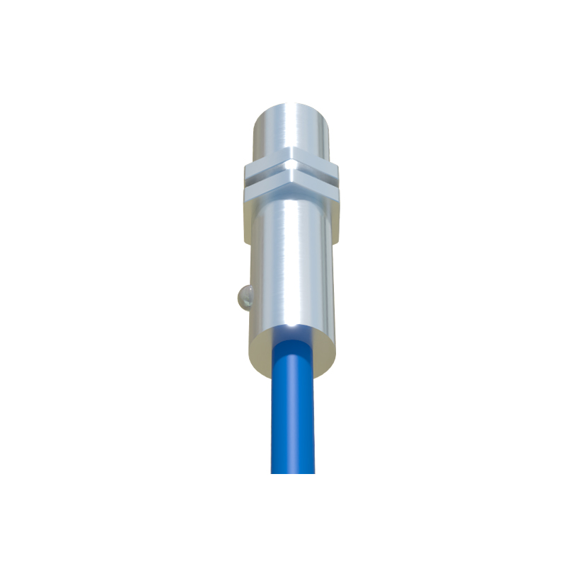
Shielded cables are frequently employed in environments with significant electromagnetic interference (EMI), such as near motor drives or welding equipment. Photographs of proper installation show the cable's braided shield connected to ground at only one end, typically at the control panel, to prevent ground loops. The shield is not connected at the sensor end, which is clearly visible in detailed images.
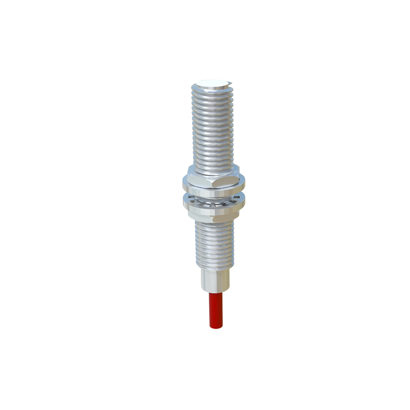
Dual-channel or safety-rated sensors with complementary outputs (e.g., for door monitoring) have more complex wiring. Real system images depict two separate output wires (often black and white) connected to safety relay modules. These images highlight the use of dedicated safety-colored cables (often yellow with a blue tracer) per international standards like ISO 13849.
Common wiring mistakes are easily identified in comparative images. One frequent error is incorrect polarity for DC sensors, which can damage the device. Another is neglecting to connect the separate drain wire (if present) in shielded cables to the ground terminal, reducing EMI protection. Over-tightening terminal screws, visible as stripped wire strands or cracked ferrules, can also cause failures.
Best practices, illustrated in clean panel photos, include: using the correct wire gauge (often 0.34 mm² to 2.5 mm²); routing sensor cables separately from high-power lines; leaving service loops for future maintenance; and applying permanent, legible wire markers at both ends of each conductor. For sensors in washdown or corrosive areas, images show the use of IP67 or IP69K rated connectors with proper gland seals to ensure integrity.
In conclusion, successful proximity sensor installation hinges on understanding the sensor type, output configuration, and application environment. The accompanying real images serve as a practical reference, translating wiring diagrams into tangible connections. Always consult the manufacturer's datasheet for the specific model, as wire colors and functions can vary. Proper wiring not only guarantees functionality but also enhances system safety and reduces downtime in industrial operations.