Proximity sensors are fundamental components in modern industrial automation, robotics, and safety systems. Their primary function is to detect the presence or absence of an object without physical contact. While much attention is given to sensing principles—inductive, capacitive, photoelectric, or ultrasonic—the underlying electrical behavior, particularly the current flow, is critical for proper selection, integration, and troubleshooting. This article delves into the current pathways within common DC-powered proximity sensors, explaining the operational states and their implications for circuit design.
At its core, a proximity sensor is an active electronic device. For DC models, which are predominant in industrial control panels, two primary wiring configurations exist: PNP (sourcing) and NPN (sinking). These terms describe the type of transistor used in the sensor's output stage and fundamentally dictate the direction of current flow from the sensor to the load (typically a programmable logic controller (PLC) input, relay, or indicator).
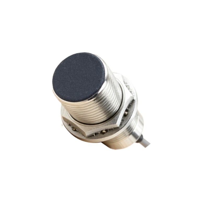
In a standard three-wire DC sensor, you will find connections for Brown (V+), Blue (V- or Common), and Black (Output). The internal circuitry consists of the oscillator and detection circuit, a signal conditioner, and the output switching element.
Current Flow in a PNP (Sourcing) Sensor:
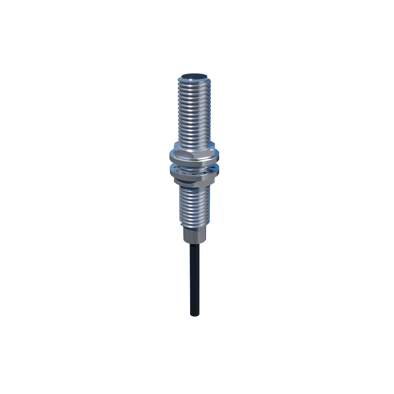
When powered (Brown to +24VDC, Blue to 0VDC), the sensor's internal circuits become active. In the absence of a target, the output transistor is in an OFF state. The Black output wire is effectively disconnected from the internal positive supply. No current flows from the sensor's output terminal to the load. When a target enters the sensing field, the detection circuit triggers, turning the PNP transistor ON. This action connects the Black wire internally to the positive supply rail (V+). Current now sources or flows out of the sensor's Black wire, through the connected load (e.g., into a PLC digital input), and completes its path back to the power supply's negative terminal (V-). The load must be connected between the sensor output and V-.
Current Flow in an NPN (Sinking) Sensor:
The power connections remain identical. However, the internal output uses an NPN transistor. In the idle state (no target), this transistor is OFF, leaving the Black output wire internally disconnected. Upon target detection, the NPN transistor switches ON. This action internally connects the Black output wire to the common or negative rail (V-). For current to flow, the load must be connected between the positive supply (V+) and the sensor's Black wire. When active, current flows from V+, through the external load, and into the sensor's Black wire, where it is sinked to the V- line. The sensor completes the circuit to ground.
Key Considerations for Current Flow:
1. Load Compatibility: Mismatching PNP and NPN sensors with the load is a common error. A PNP sensor cannot drive a load connected to V+; it requires the load to reference V-. Conversely, an NPN sensor requires the load to be connected to V+.
2. Leakage Current: Even in the OFF state, a small leakage current (typically microamps to a few milliamps) may flow through the sensor's output due to protective circuits or semiconductor characteristics. This current must be considered when interfacing with high-impedance PLC inputs, as it may be sufficient to falsely indicate an ON state. Using a bleeder resistor across the load can mitigate this.
3. Inrush Current: During the initial power-up or immediately after switching, a momentary surge of current higher than the steady-state operating current can occur as internal capacitors charge. Power supply and circuit protection must accommodate this.
4. Short-Circuit Protection: Modern sensors incorporate electronic protection that limits output current during a short-circuit event. This protection circuitry actively regulates the current flow to prevent damage, often by going into a hiccup mode or current limiting until the fault is cleared.
5. Current Consumption vs. Output Current: It is vital to distinguish between the sensor's own operating current (drawn between Brown and Blue wires) and its rated output switching current (through the Black wire). The power supply must be sized for the sum of all device currents in the system.
6. Wiring and Voltage Drop: Using undersized wires over long distances can cause significant voltage drop due to wire resistance. This reduces the voltage at the sensor and load, potentially affecting the sensing distance and the ability of the output transistor to saturate fully, leading to erratic operation or increased heat dissipation in the sensor.
Understanding these current paths is not merely academic. It directly impacts system reliability. For instance, in a multi-sensor installation, ensuring consistent wiring (all