In the realm of industrial automation and control systems, proximity sensors are indispensable components for non-contact detection of objects. Among the various types available, three-wire DC proximity sensors are particularly prevalent due to their straightforward integration and reliable performance. A fundamental aspect of their application lies in understanding the distinction between Normally Open (NO) and Normally Closed (NC) output configurations. This knowledge is critical for proper circuit design, safety considerations, and system functionality.
A three-wire proximity sensor typically comprises three distinct wires: a brown wire for the positive DC supply voltage (often +24V DC), a blue wire for the common negative or 0V, and a black wire which serves as the signal output line. The internal switching element, usually a solid-state transistor (NPN or PNP), controls this output. The core operational principle remains consistent: when a target enters the sensor's detection range, its internal oscillator circuit is damped, triggering a change in the output state. The designation "Normally Open" or "Normally Closed" describes the electrical state of this output signal wire relative to the supply wires when the sensor is in its idle, non-activated state—that is, when no target is present.
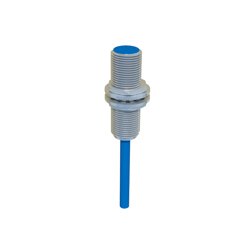
A Normally Open (NO) configuration is the most common. In this setup, when the sensor is powered but not detecting a target, the output transistor is in an "off" state. This means there is an open circuit between the black output wire and either the positive supply (for a PNP sensor) or the negative supply (for an NPN sensor). Essentially, no signal current flows. When a target enters the sensing field, the transistor switches "on," closing the circuit and allowing current to flow through the output. In a typical control logic, this activation creates a signal path to a PLC input module, a relay coil, or an indicator lamp. For instance, an NO sensor might be used to start a counter when an object passes by, or to signal a machine to begin a cycle only when a part is confirmed in place.
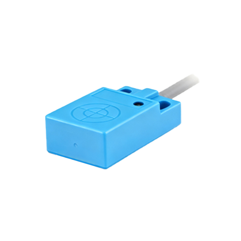
Conversely, a Normally Closed (NC) configuration operates in the opposite manner. When the sensor is idle with no target present, the output transistor is "on," maintaining a closed circuit and allowing current to flow continuously through the output line. Upon detecting a target, the transistor switches "off," opening the circuit and stopping the current flow. This configuration is often employed in safety-critical or monitoring applications. A classic example is a guard door monitoring system. An NC sensor on the door would continuously send a "safe" signal (current flowing) to the machine controller while the door is closed. If the door is opened, the sensor activates (target moves away), breaks the circuit, and sends a "stop" signal, halting the machine immediately. This fail-safe design ensures that a wire break or power loss to the sensor also results in an open circuit, mimicking the "door open" state and triggering a safe shutdown.
The choice between NO and NC is not merely a preference but a deliberate design decision with significant implications. Key factors influencing the selection include:
1. Safety and Fail-Safe Requirements: NC contacts are inherently fail-safe for stop functions, as a fault (broken wire, loss of power) causes the signal to be lost, initiating a safe state. NO contacts are not fail-safe in this manner.
2. Control Logic and Energy Efficiency: NO sensors consume power only when activated, which can be beneficial for energy savings. NC sensors draw a continuous holding current when idle.
3. PLC Programming Convenience: The logic in a Programmable Logic Controller (PLC) must be written to interpret the sensor's signal correctly. An NO sensor's action (on when detected) often aligns intuitively with "presence" logic, while an NC signal may require a normally closed contact instruction in the ladder logic to achieve the same functional result.
4. Circuit Design and Wiring: The wiring to the load (e.g., PLC input) differs. For a sinking (NPN) sensor, the NO output connects the load to 0V when active. For a sourcing (PNP) sensor, it connects the load to +V when active. NC configurations reverse this idle-state connection.
It is also crucial to distinguish the sensor's output type (NPN vs. PNP) from its contact state (NO vs. NC). NPN and PNP describe the polarity of the transistor and thus whether the output switches the negative or positive side of the load. NO and NC describe the logical state of that switch. A sensor can be, for example, an NPN Normally Open or a PNP Normally Closed device. Misunderstanding this can lead to incorrect wiring and system malfunctions.
In summary, the selection of a three-wire proximity