Infrared proximity sensors are pivotal components in modern automation and electronic systems, offering non-contact detection capabilities through infrared light. This article delves into the real-world images of these sensors, examining their structural design, operational principles, and practical applications. A typical infrared proximity sensor consists of an IR emitter, a photodiode or phototransistor receiver, and signal processing circuitry. In real images, the emitter is often visible as a small, transparent or dark lens, while the receiver appears adjacent, sometimes shielded to minimize ambient light interference. The housing, usually made of black thermoplastic, helps reduce false triggers by blocking external IR sources.
Upon closer inspection of high-resolution images, one can observe the compact PCB layout, where surface-mount components like resistors, capacitors, and ICs are densely arranged. The IR LED emits light at wavelengths around 850-950 nm, which is invisible to the human eye but detectable by the receiver. When an object approaches, the reflected IR light intensity changes, triggering the sensor's output. Real images often showcase sensors with adjustable potentiometers for sensitivity calibration, allowing fine-tuning based on environmental conditions.
In industrial settings, these sensors are integrated into machinery for object detection, counting, or position sensing. Automotive applications include parking assistance systems, where sensors mounted on bumpers provide real-time proximity feedback. Consumer electronics, such as smartphones and robots, utilize miniaturized versions for touchless gesture control or obstacle avoidance. The images reveal robust designs with IP-rated enclosures for dust and water resistance, ensuring reliability in harsh environments.
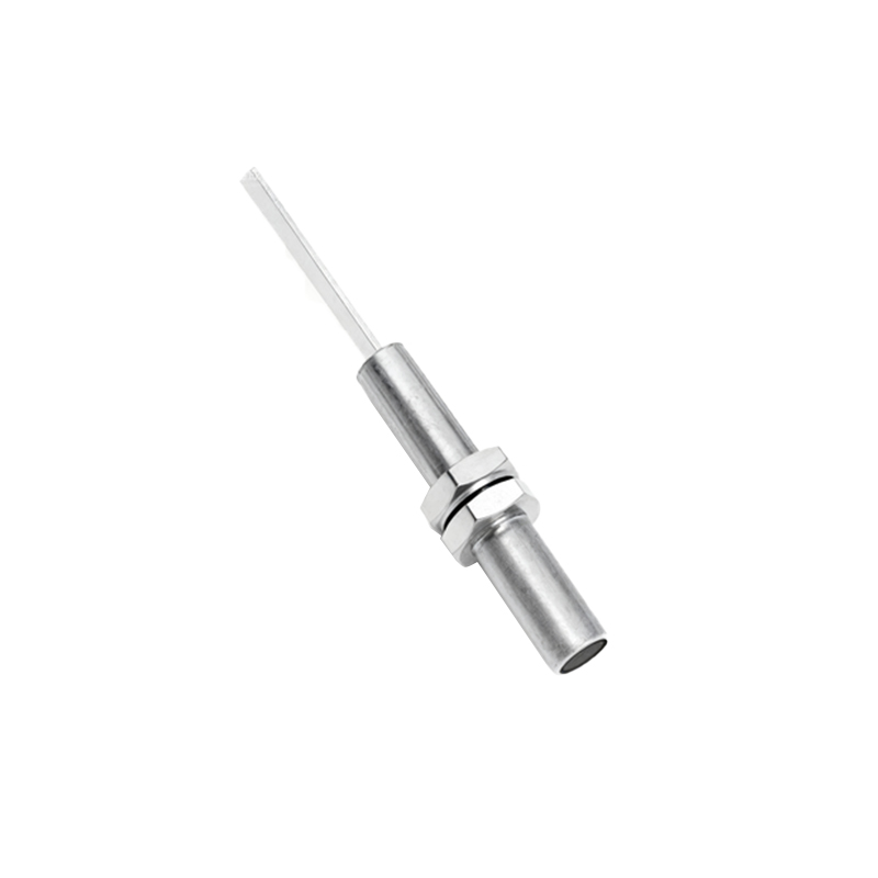
Technical analysis of the images highlights key features like response time, which can be as fast as milliseconds, and detection ranges varying from a few centimeters to several meters. The sensor's output may be analog (voltage-based) or digital (TTL/CMOS), with some models offering I2C or UART interfaces for microcontroller communication. Engineers can identify component quality through real images—for instance, gold-plated connectors indicate corrosion resistance, while thermal pads suggest efficient heat dissipation.
Common challenges visible in real images include lens contamination, which can scatter IR light and reduce accuracy, and misalignment between emitter and receiver, leading to dead zones. Proper installation, as depicted in application photos, involves aligning the sensor perpendicular to the target surface and avoiding reflective backgrounds. Maintenance tips, such as periodic cleaning with alcohol wipes, are often emphasized in technical documentation accompanying these images.
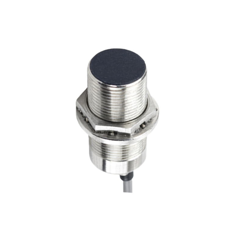
In summary, real images of infrared proximity sensors provide invaluable insights into their construction and functionality. By studying these visuals, engineers can optimize integration, troubleshoot issues, and select appropriate models for specific tasks. As technology advances, newer sensors with enhanced features like multi-zone detection and AI compatibility are emerging, further expanding their utility across industries.