Proximity switches, as non-contact sensing devices, have become indispensable components in modern industrial automation, robotics, and safety systems. Their core function is to detect the presence or absence of a target object without physical contact, offering superior reliability, longevity, and speed compared to mechanical limit switches. Understanding the principles behind their sensor connections is crucial for proper selection, installation, and troubleshooting in any control system.
At its heart, a proximity switch consists of an oscillator, a sensing coil (or electrode for capacitive types), a signal conditioner, and a solid-state output switch. The operating principle varies by type. Inductive proximity switches generate a high-frequency electromagnetic field via the oscillator and coil. When a metallic target enters this field, eddy currents are induced on the target's surface, which dampens the oscillation amplitude. The internal detection circuit monitors this change and triggers the output state. Capacitive proximity switches operate similarly but generate an electrostatic field. They can detect both metallic and non-metallic materials (like plastic, wood, or liquid) by sensing changes in capacitance caused by the target altering the dielectric constant of the field. Ultrasonic and photoelectric types use different physical principles (sound waves and light beams, respectively) but share the same core concept: a non-contact detection event that is converted into an electrical signal change.
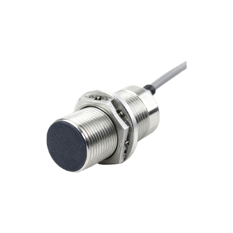
The connection of the proximity switch sensor to the control system is where the electrical interface is defined. Most industrial proximity switches are 3-wire or 2-wire DC devices, with 4-wire versions offering dual outputs. The 3-wire configuration is the most common, comprising a positive supply wire (typically brown), a negative/ground wire (blue), and a switched output wire (black for NPN, black or white for PNP). NPN (sinking) outputs switch the negative (0V) line to the load, meaning the load is connected between the output wire and the positive supply. Conversely, PNP (sourcing) outputs switch the positive line to the load, with the load connected between the output and ground. The choice between NPN and PNP is fundamental and depends on the input circuit of the connected controller (e.g., PLC). Asian and European systems often favor PNP, while NPN is common in some regions; always verify the controller's specifications.
Two-wire proximity switches are simpler, acting like a switch in series with the power supply and load. They are easier to wire but have a residual voltage drop when "on" and a small leakage current when "off," which must be considered for compatibility with highly sensitive PLC inputs. Four-wire devices combine both an NPN and a PNP output in one housing, providing wiring flexibility.
The electrical characteristics of the connection are paramount. Key parameters include the supply voltage range (e.g., 10-30V DC), output current rating, switching frequency, and protection features like short-circuit, reverse polarity, and overload protection. Proper wiring is essential: use shielded cables in electrically noisy environments, grounding the shield at the controller end only. Maintain proper clearance between cables carrying high currents and sensor wires to prevent inductive interference. For DC sensors, always observe correct polarity to avoid damage.
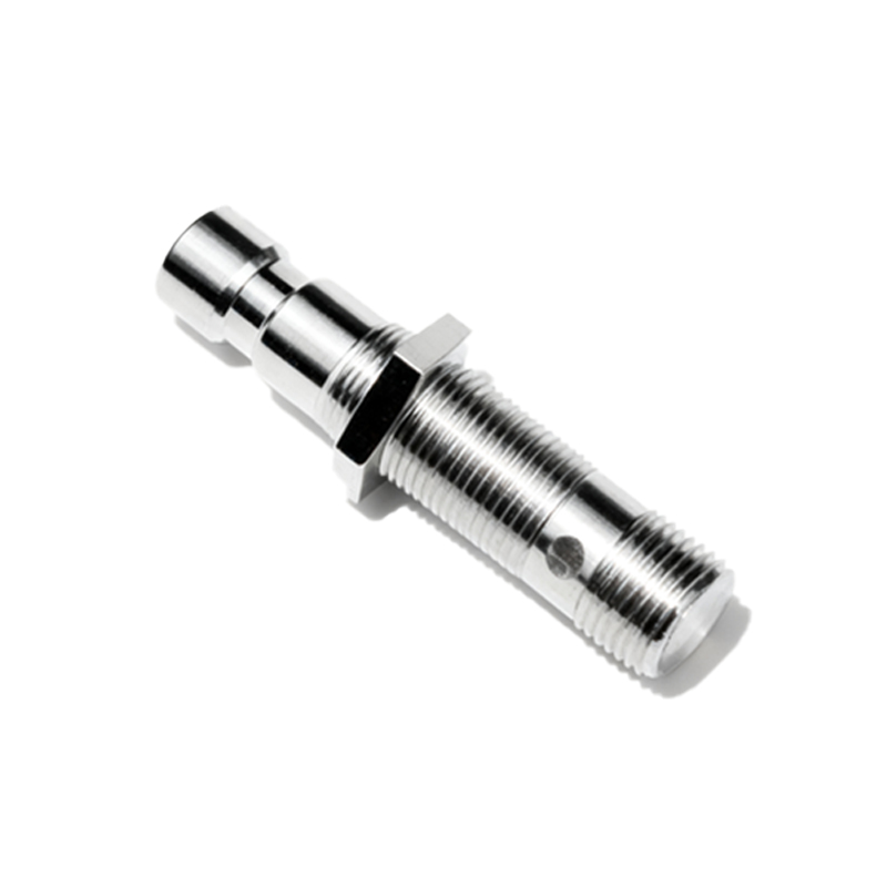
In application, the sensor's output is typically connected to a programmable logic controller (PLC) digital input module, a relay, or an indicator. When the target is detected, the internal solid-state switch (usually a transistor) changes state, allowing current to flow (or stop flowing) through the output circuit. This creates a clean, bounce-free signal for the PLC. The connection is not merely about making a circuit; it's about ensuring signal integrity, immunity to electromagnetic interference (EMI), and system safety. For instance, in safety-critical applications, redundant sensors with diverse connection paths or safety-rated relays may be employed.
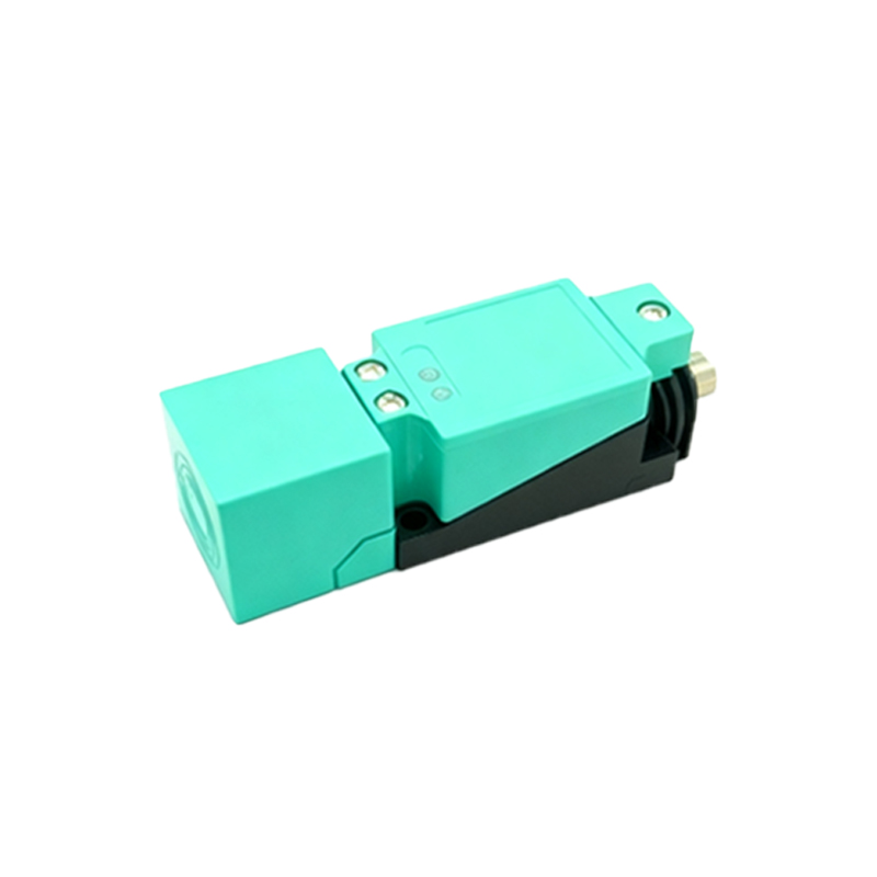
Installation considerations directly impact the sensor connection's performance. Factors such as sensing distance (rated and effective), target material, size, and approach direction must be accounted for. Mounting metal-to-metal sensors require a non-ferrous mounting bracket or a specific clearance to prevent the mounting material from influencing the sensing field. Proper alignment and avoidance of multiple adjacent sensors interfering with each other (mutual interference) are also critical.
In summary, the connection of a proximity switch sensor is a systematic integration of its internal detection principle with the external control circuitry. A deep understanding of the sensor's type (inductive/capacitive), output configuration (NPN/PNP/2-wire), electrical specs, and installation requirements ensures a robust, reliable, and maintenance-free link within the automation system. This knowledge empowers engineers to design efficient control logic and swiftly diagnose issues, from faulty wiring to incompatible load connections, thereby maximizing uptime and system performance.