In industrial automation and control systems, proximity sensors play a critical role in detecting the presence or absence of objects without physical contact. Proper wiring and connection are essential to ensure reliable operation, safety, and system integration. This article provides a comprehensive guide on connecting proximity sensors, supported by wiring diagrams and visual references to assist engineers and technicians in the field.
Proximity sensors are commonly categorized into inductive, capacitive, and magnetic types, each suited for specific applications. Inductive sensors detect metallic objects, capacitive sensors handle non-metallic materials, and magnetic sensors are used with permanent magnets. Regardless of type, most proximity sensors share similar wiring principles, typically involving power supply connections, output signals, and grounding.
A standard three-wire DC proximity sensor includes brown (positive), blue (negative), and black (output) wires. The brown wire connects to the positive terminal of the DC power supply, usually ranging from 10-30 VDC. The blue wire is linked to the negative terminal or ground. The black wire delivers the output signal, which can be either normally open (NO) or normally closed (NC), to a controller like a PLC. For two-wire AC sensors, wiring involves connecting one wire to the AC power source and the other to the load, simplifying installation but requiring careful current matching.
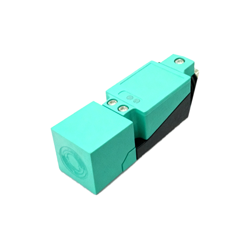
Wiring diagrams are invaluable tools for visualizing connections. For instance, in a typical setup with a PLC, the sensor’s output wire connects to an input module, while the power supply is shared across multiple sensors to optimize efficiency. Shielded cables are recommended for environments with electromagnetic interference to prevent false triggers. Additionally, ensuring proper cable routing away from high-voltage lines reduces noise and enhances signal integrity.
When connecting multiple sensors, consider using a common grounding point to avoid ground loops, which can cause erratic behavior. It’s also crucial to verify the sensor’s specifications, such as switching current and voltage ratings, to prevent overloads. For hazardous areas, intrinsically safe barriers may be required to limit energy and prevent ignition risks.
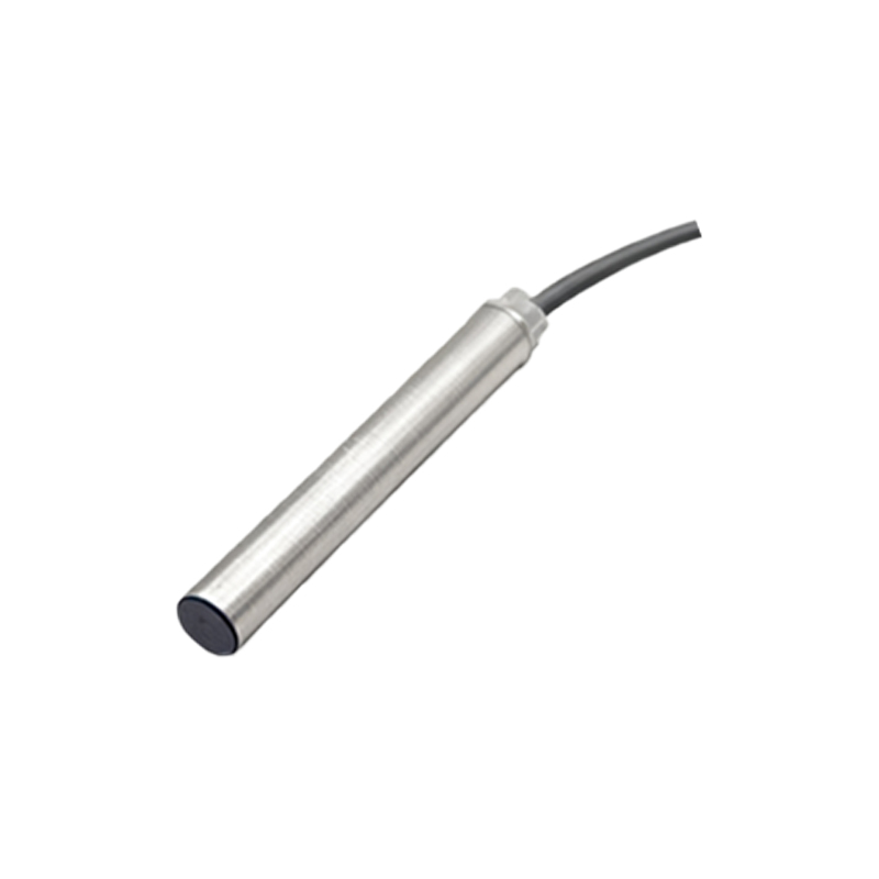
Visual guides, including labeled images and schematic diagrams, help clarify complex setups. For example, a diagram showing sensor connections to a relay or timer illustrates how to integrate sensors into broader control circuits. Photos of actual installations highlight best practices, such as using waterproof connectors in damp conditions or securing cables with clamps to prevent strain.
Testing connections with a multimeter before powering up ensures correct polarity and continuity. After installation, calibrate sensors by adjusting the sensing distance as per manufacturer guidelines, especially for capacitive models detecting varied materials. Regular maintenance, like cleaning sensor faces and inspecting wires for damage, prolongs lifespan and prevents downtime.
In summary, connecting proximity sensors correctly involves understanding wiring standards, utilizing diagrams for accuracy, and adhering to safety protocols. With clear visual aids and systematic approaches, engineers can achieve robust sensor integration, enhancing automation system performance and reliability across industries like manufacturing, packaging, and automotive.