In industrial automation and control systems, proximity sensors are indispensable components for non-contact detection of metallic or, in some cases, non-metallic objects. Their reliability is paramount for ensuring smooth production flow, safety, and machine integrity. However, a persistent and disruptive fault that maintenance engineers frequently encounter is the "fails to deactivate" or "stuck on" condition. This article delves into the root causes, systematic diagnostic procedures, and effective solutions for this critical malfunction, presented from a seasoned engineering perspective.
A proximity sensor that remains in an active state—continuously sending an output signal even when the target object has moved out of its sensing range—can cause cascading failures. It may prevent a machine cycle from completing, cause jams in material handling systems, or create hazardous conditions by falsely indicating a clear path. Understanding the underlying technology is the first step in troubleshooting. Inductive proximity sensors, the most common type for metal detection, generate an electromagnetic field. A metallic target entering this field induces eddy currents, causing a change in the sensor's internal oscillation amplitude, which the circuitry detects and converts into a switched output. Capacitive sensors operate on a similar principle but react to changes in capacitance caused by various materials.
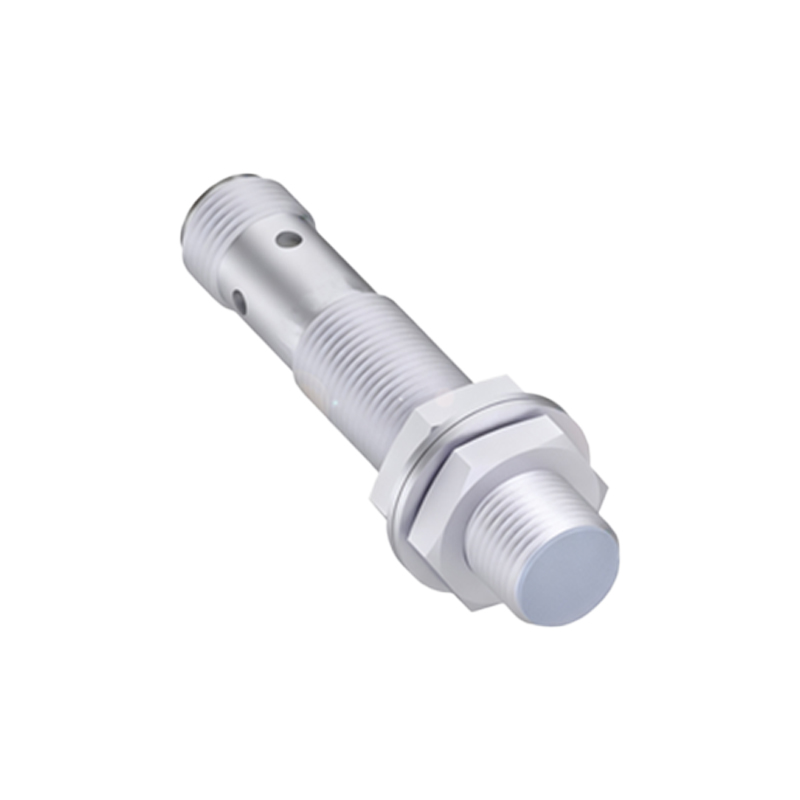
The primary culprits behind a sensor failing to deactivate can be categorized into environmental, electrical, mechanical, and internal failures.
Environmental Factors: Industrial environments are harsh. Accumulation of metallic swarf, dust, or conductive debris on or around the sensor's active face can effectively become a permanent "target." For inductive sensors, fine ferrous powder can agglomerate and mimic a solid metal object. Similarly, for capacitive sensors, buildup of moisture, oil, or other materials can alter the dielectric constant, leading to a constant activated state. Chemical contamination can also degrade the sensor's housing or potting material, allowing moisture ingress that affects internal electronics.
Electrical Issues: Electrical problems are a frequent source of failure. Voltage spikes or transients on the supply line, often from inductive loads like solenoids or motors switching nearby, can damage the sensor's output switching element (typically a transistor). A damaged transistor can fail shorted, providing a permanent output. Incorrect wiring, such as a short circuit between the output wire and the positive supply, will also cause a constant output signal. Ground loops or excessive electromagnetic interference (EMI) from variable frequency drives (VFDs) or welding equipment can induce false signals in the sensor's circuitry.
Mechanical and Installation Problems: Improper mounting is a common, yet overlooked, cause. If the sensor is mounted too close to a stationary metal structure (like the machine frame), this metal becomes the sensed target. Vibration can cause this gap to vary, sometimes creating an intermittent fault that appears as a "stuck on" condition. Physical damage to the sensing face or housing from impacts can also alter its characteristics.
Internal Sensor Failure: Like any electronic device, proximity sensors have a finite lifespan. Component degradation over time, particularly the output transistor under constant load, can lead to failure. Internal oscillation circuit failure can also cause the sensor to latch in one state.
A Structured Diagnostic Approach:
1. Visual Inspection: Begin with a thorough visual check. Look for physical damage, debris accumulation, and correct mounting alignment. Clean the sensor face meticulously.
2. Isolation Test: The most definitive test is to electrically isolate the sensor. Disconnect the output wire from the PLC or controller. Using a multimeter in voltage or continuity mode (depending on the sensor type—PNP/NPN), measure the output directly at the sensor's terminals while bringing a target into and out of range. If the output state changes correctly, the fault lies in the wiring or the load (PLC input). If it remains constant, the sensor is faulty.
3. Supply Voltage Check: Measure the supply voltage at the sensor's terminals under load. Ensure it is within the specified range (e.g., 10-30 VDC). A low voltage can cause erratic behavior.
4. Load Check: Verify the load on the sensor (usually the PLC input impedance) does not exceed its rated maximum current.
5. Substitution: If possible, replace the suspect sensor with a known-good unit of the same model. This is a quick way to confirm the diagnosis.
Solutions and Best Practices:
Selection and Protection: Choose sensors with appropriate IP (Ingress Protection) and IK (Impact Protection) ratings for the environment. Use sensors with built-in protection against short circuits, overloads, and reverse polarity. For areas with heavy EMI, select models with robust shielding or consider using DC sensors with analog current outputs (4-20mA) which are less susceptible to noise.
Installation Discipline: Maintain the recommended mounting distances from surrounding metal