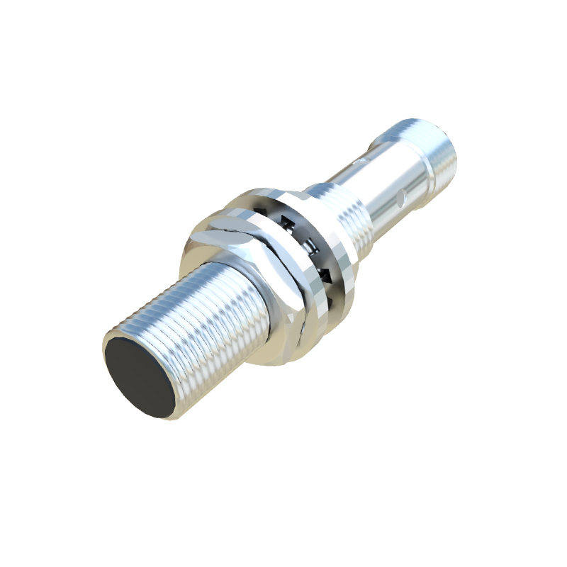
In industrial automation and control systems, proximity switches are indispensable components for detecting the presence or absence of objects without physical contact. Among the various wiring configurations, the three-wire method stands out as a widely adopted standard due to its reliability and compatibility with modern programmable logic controllers (PLCs). This article delves into the principles, wiring procedures, and practical considerations for implementing three-wire proximity switches, tailored for electrical engineers and technicians.
Proximity switches operate based on electromagnetic, capacitive, or inductive principles, with inductive types being the most common in industrial settings. A three-wire proximity switch typically includes three distinct wires: brown (positive supply), blue (negative or common), and black (output signal). The brown wire connects to the positive terminal of a DC power supply, usually ranging from 10 to 30 volts DC, depending on the sensor specifications. The blue wire is linked to the negative or ground terminal, establishing a complete circuit for power. The black wire serves as the output, transmitting a signal to the control device—such as a PLC, relay, or counter—when an object is detected within the sensor's sensing range.
Wiring a three-wire proximity switch requires attention to detail to ensure optimal performance and safety. First, verify the power supply voltage matches the sensor's rated voltage, as incorrect voltage can lead to malfunction or damage. Connect the brown wire to the positive supply and the blue wire to the negative supply, ensuring secure connections to prevent loose contacts that might cause intermittent faults. The black output wire should be connected to the input module of the control system. For normally open (NO) configurations, the output circuit closes upon detection, allowing current flow to the control device. Conversely, normally closed (NC) configurations open the circuit upon detection. It is crucial to consult the sensor datasheet to confirm the output type and wiring diagram, as variations exist among manufacturers.
In practice, three-wire proximity switches offer advantages over two-wire versions, including lower leakage current and higher switching accuracy. They are less susceptible to voltage drops and can handle higher loads, making them suitable for demanding industrial environments. However, engineers must consider factors like sensing distance, environmental conditions (e.g., temperature, humidity, and electromagnetic interference), and installation orientation. For instance, metallic objects near the sensor might affect inductive types, while dust or liquids could impact capacitive sensors. Proper shielding and mounting techniques, such as using non-metallic brackets, can mitigate these issues.
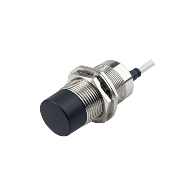
Maintenance and troubleshooting are integral to sustaining system reliability. Common problems with three-wire proximity switches include false triggering, no output signal, or erratic behavior. To diagnose, use a multimeter to check voltage levels at the brown and blue wires, ensuring the power supply is stable. Test the output signal by placing a target object within range and measuring voltage on the black wire; a change indicates proper operation. If issues persist, inspect for wiring errors, sensor damage, or environmental factors. Regular calibration and cleaning of the sensor face can prolong its lifespan and maintain accuracy.
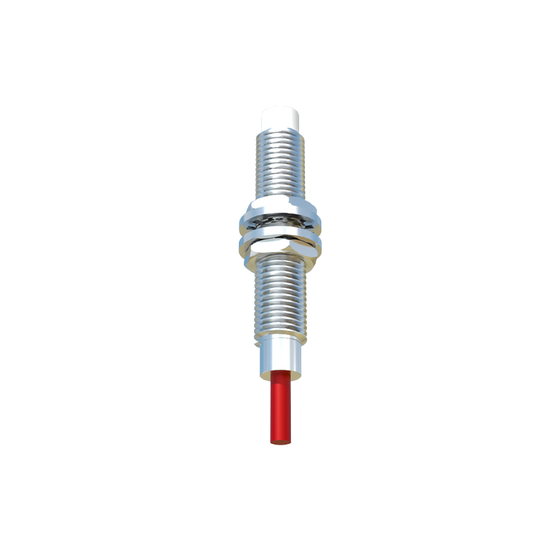
In summary, the three-wire wiring method for proximity switches provides a robust solution for object detection in automation systems. By adhering to standard procedures and considering operational nuances, engineers can enhance system efficiency and reduce downtime. As technology evolves, integrating smart sensors with diagnostic capabilities may further simplify wiring and maintenance, but the foundational principles of three-wire configurations will remain relevant in industrial applications.