Proximity sensors are indispensable components in modern industrial automation, providing non-contact detection of metallic or other target objects. A correct and reliable wiring connection is fundamental to their operation, safety, and longevity. This guide details the standard wiring configurations for common types of proximity sensor switches, focusing on practical implementation and industry best practices.
The core of proximity sensor wiring involves connecting three or four primary terminals: the power supply lines and the output signal line. The most prevalent types are 3-wire and 4-wire DC sensors, with 2-wire AC/DC sensors also in use. We will concentrate on the widely adopted 3-wire DC configuration.
Understanding the Terminals
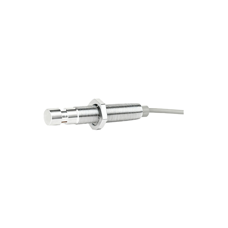
A typical 3-wire DC proximity sensor has clearly labeled terminals:
Brown Wire (or L+): This is the positive power supply line. It must be connected to the positive terminal of the DC power source (e.g., 10-30V DC).
Blue Wire (or L- or N): This is the negative power supply line (0V). It must be connected to the negative terminal or common ground of the DC power source.
Black Wire (or OUT): This is the switched output signal line. The state of this line (ON or OFF) changes based on the presence or absence of the target.
Wiring Configurations: NPN vs. PNP
The critical distinction lies in the type of transistor used in the sensor's output stage, determining how the output signal interacts with the load (e.g., a PLC input, relay, or indicator lamp).
1. PNP Sourcing Output (Also known as "Positive Switching")
Operation: In a PNP sensor, the black output wire acts as a sourcing output. When the sensor detects a target, it internally connects the black wire to the positive supply (brown wire), sourcing current from the sensor to the load.
Wiring Diagram: Connect the brown wire to DC+, blue wire to DC-. Connect the black wire to one terminal of your load (e.g., PLC input module). Connect the other terminal of the load back to DC- (common ground). Current flows from DC+ -> Sensor (internally) -> Black Wire -> Load -> DC-.
Typical Use: Commonly used with PLCs and controllers in Europe and many regions, where the PLC input card is designed to receive a positive signal.
2. NPN Sinking Output (Also known as "Negative Switching")
Operation: In an NPN sensor, the black output wire acts as a sinking output. When activated, it internally connects the black wire to the negative supply (blue wire), sinking current from the load into the sensor.
Wiring Diagram: Connect brown to DC+, blue to DC-. Connect one terminal of your load to DC+. Connect the other terminal of the load to the black wire of the sensor. Current flows from DC+ -> Load -> Black Wire -> Sensor (internally) -> DC-.
Typical Use: Prevalent in Asia and Japan, compatible with PLC input cards configured to be activated by a connection to ground.
4-Wire DC Sensors simply combine one PNP (sourcing) and one NPN (sinking) output in a single housing, offering maximum flexibility. The fourth wire is typically white and provides the complementary output.
2-Wire Sensors are simpler, acting like a switch in series with the power line and load. They are polarity-insensitive for AC models but must be observed for DC types.
Essential Wiring Practices
1. Power Supply: Always use a stable, regulated DC power supply within the sensor's rated voltage range (e.g., 12-24V DC). Ripple and noise can cause erratic operation.
2. Load Compatibility: Ensure the load's current draw does not exceed the sensor's maximum switching capacity. For inductive loads like relays, use a protective diode (flyback diode) across the coil to suppress voltage spikes.
3. Shielding & Routing: In electrically noisy environments, use shielded cables. Ground the shield at only one end (typically the control panel end). Route sensor cables away from high-voltage power lines and motor drives.
4. Short-Circuit Protection: While many sensors have built-in protection, incorporating a fast-acting fuse (e.g., 1-2A) in the supply line is a recommended safety measure.
5. Consult the Datasheet: Always refer to the manufacturer's datasheet for the specific pinout, wiring diagram, and specifications of your sensor model, as colors and markings can occasionally