In industrial automation and control systems, proximity sensors play a critical role in detecting the presence or absence of objects without physical contact. Among the various feedback mechanisms, the status indicator—often a small LED on the sensor housing—serves as a primary visual cue for operational health and detection events. A common scenario observed by engineers and technicians is the transition of this indicator from a steady or blinking red light to a solid green light. Understanding what this color change signifies is essential for efficient troubleshooting, maintenance, and system optimization.
Typically, a proximity sensor's LED indicator is designed to communicate specific states based on color and blinking patterns. While manufacturer-specific variations exist, a general industry convention has emerged. A red indicator often signifies one of several conditions: it may indicate that the sensor is powered and in a standby state (awaiting a target), that it is in an error or fault mode (such as wiring issues, short circuits, or internal failures), or, in some models, that a target object is within the sensing range. Conversely, a green light universally symbolizes a "normal" or "optimal" condition. The transition from red to green, therefore, marks a shift from an initial or non-ideal state to a confirmed, proper operational state.
Let's delve into the most frequent instances where this red-to-green transition occurs and its interpretation.
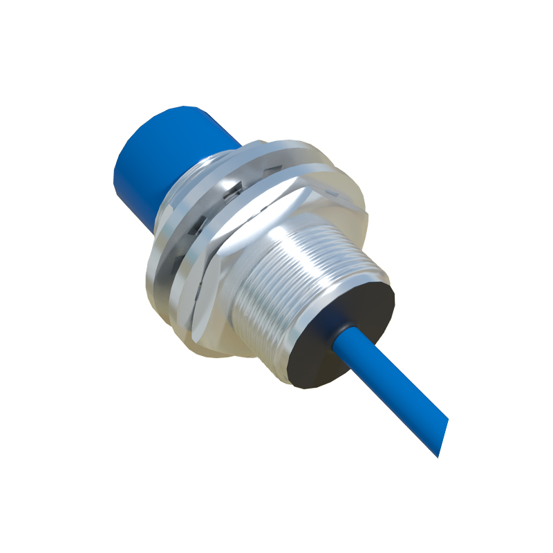
1. Power-On Initialization Sequence
Upon applying power, many modern inductive, capacitive, or photoelectric proximity sensors undergo a brief self-check or initialization routine. During this period, which may last a few milliseconds to a couple of seconds, the LED might illuminate red. This red light indicates the sensor is energizing its internal circuitry and performing diagnostic checks. Once the initialization is successfully completed and the sensor is ready for operation, the indicator will switch to green. This steady green light confirms that the sensor is powered correctly, is functionally healthy, and is now actively monitoring its sensing field. Failure to transition to green after power-up could point to insufficient voltage, incorrect wiring, or a hardware fault.
2. Target Detection Event (Depends on Configuration)
The interpretation of colors during actual detection can vary significantly based on the sensor's output configuration (Normally Open/NO or Normally Closed/NC) and the manufacturer's programming. In a very common setup for a sinking (NPN) or sourcing (PNP) DC sensor with a NO configuration:
- No Target Present: The output transistor is off. The LED might show green, indicating a "ready" state with no active detection.
- Target Enters Sensing Range: The output transistor switches on. The LED immediately changes from green to red, providing a visual confirmation that the sensor has detected an object and its output is active.
However, the inverse is also widely used. Some sensors are designed where a red light indicates "standby" or "power on," and a green light activates only upon successful target detection. In this design, the transition from red to green is the direct visual signal of a detection event. It is paramount to consult the specific sensor's datasheet or manual to decode its indicator language accurately. Misinterpretation can lead to incorrect assumptions about system logic.
3. Resolution of a Fault Condition
A solid or flashing red light can denote a fault. Examples include overload conditions, excessive temperature, sensing distance drift beyond calibration limits, or electrical noise interference. When such a fault is present, the sensor may inhibit its output or operate unreliably. Once the underlying issue is rectified—for instance, removing a short circuit, reducing ambient temperature, or securing a loose connection—the sensor will automatically clear the fault flag. This resolution is often visually confirmed by the indicator changing from red back to a steady green. This transition assures the operator that the sensor has returned to its normal operating parameters.
4. Mode Switching or Teach-In Procedures
Many programmable proximity sensors feature a "teach-in" function to set the sensing distance or output parameters. Entering this programming mode is frequently signaled by a specific LED sequence, often involving red illumination. Once the programming steps are successfully completed and the sensor saves the new settings and exits the mode, the indicator will typically revert to a solid green, confirming the sensor is now operational with the new configuration.
Best Practices for Engineers and Technicians:
- Always Reference Documentation: Never assume the color code. The first step when installing or troubleshooting should be to review the product manual for the definitive indicator status table.
- Consider the System Context: Observe the transition in relation to the machine cycle. Does the change coincide with a part arriving at the station? Does it occur right after power-up? Context is key to correct diagnosis.
- Use as a Diagnostic Aid: A sensor that fails to transition from red to green when expected