In industrial automation and process control, the proper installation and wiring of proximity switch sensors are critical for ensuring the reliable operation of centrifuges. These sensors, often inductive or capacitive types, detect the presence or position of rotating components without physical contact, making them ideal for high-speed applications like centrifugation. This guide provides a step-by-step approach to wiring a proximity switch sensor for centrifuge systems, adhering to standard electrical practices and safety protocols.
First, identify the sensor type and specifications. Common proximity switches for centrifuges include 2-wire, 3-wire, and 4-wire configurations, with DC or AC power options. Check the manufacturer's datasheet for voltage ratings (e.g., 10-30V DC or 90-250V AC), output type (PNP or NPN for DC sensors), and current capacity. Ensure compatibility with the centrifuge's control system, such as PLCs or relay modules. For centrifuges, sensors are typically mounted near the rotor or shaft to monitor speed, position, or imbalance.
Begin by disconnecting power to the centrifuge and verifying lockout/tagout procedures to prevent accidental energization. Mount the sensor securely using brackets or threaded housings, aligning it within the sensing range (usually 2-15 mm for inductive sensors). Avoid metallic obstructions that could interfere with detection. For wiring, use shielded cables to minimize electromagnetic interference from the centrifuge's motor.
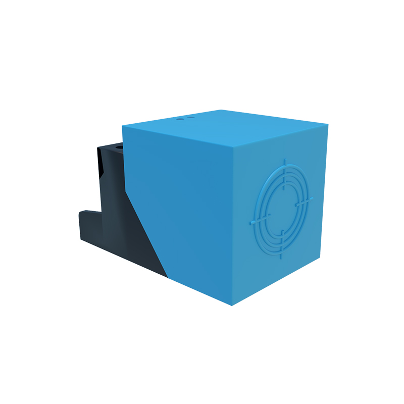
For a 3-wire DC proximity sensor (the most common type), connect the wires as follows:
- Brown wire: Connect to the positive DC supply voltage (e.g., +24V).
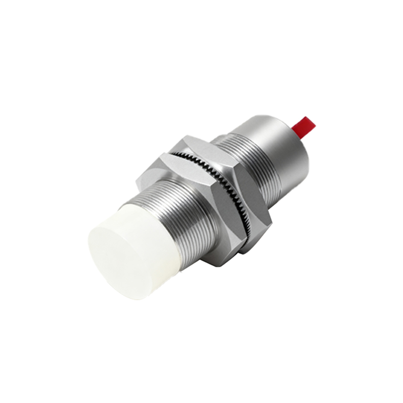
- Blue wire: Connect to the negative DC supply or ground (0V).
- Black wire: This is the output signal wire. For PNP sensors, connect it to the load (e.g., PLC input), which then links to ground. For NPN sensors, connect the load to the positive supply, with the output sinking to ground.
Incorporate protective devices such as fuses or circuit breakers in the power line to prevent overloads. If using multiple sensors, wire them in parallel to avoid signal conflicts. For AC sensors, typically with two wires, connect one wire to the live AC terminal and the other to the load, ensuring proper insulation.
After wiring, test the sensor by slowly rotating the centrifuge manually or at low speed. Use a multimeter to verify output voltage changes when the target (e.g., a metal bolt on the rotor) passes the sensor. Adjust the sensor position if detection is inconsistent. Once confirmed, integrate the sensor into the centrifuge's control loop for functions like speed monitoring, automatic braking, or safety shutoffs.
Regular maintenance includes checking connections for corrosion or loosening, especially in environments with vibration or moisture. Follow industry standards such as IEC 60947-5-2 for proximity switches and NFPA 70 for electrical safety. Improper wiring can lead to sensor failure, false triggers, or centrifuge damage, so always double-check diagrams and consult experts if needed.
By following these guidelines, engineers can ensure precise and safe sensor integration, enhancing centrifuge performance and longevity in applications like laboratory research, pharmaceutical production, or wastewater treatment.